
Imaging device

a technology of optical viewfinder and image, which is applied in the direction of exposure control, printers, camera focusing arrangement, etc., can solve the problems of difficult to designate peak contrast, difficult to identify peak contrast, and difficult to use focal point adjustment, etc., to achieve convenient use and easy to confirm a difference

Active Publication Date: 2012-03-20
PANASONIC INTELLECTUAL PROPERTY CORP OF AMERICA
View PDF4 Cites 14 Cited by
  • Summary
  • Abstract
  • Description
  • Claims
  • Application Information

AI Technical Summary

Benefits of technology

[0013]It is another object to improve convenience in an imaging device having an aperture value update function.
[0015]With this imaging device, since the aperture value is adjusted to be at or below the set aperture value before the focal state of the optical image is adjusted by the focal point adjuster, if the set aperture value is relatively small, for example, the subject field depth will be shallow when focal point adjustment is performed by contrast detection method. Since the contrast is higher when the subject field depth is shallower, the precision of auto focusing by contrast detection method is higher. Consequently, stable focal point adjustment is possible regardless of the aperture value prior to focal point adjustment.
[0024]With this imaging device, since the focal state is adjusted after the start of the depth-of-field preview mode, the subject field depth can be checked using an image that is more or less in focus. Consequently, it is easier to confirm a difference between images due to a difference in aperture value, so the device is more convenient to use.

Problems solved by technology

However, imaging with an optical viewfinder is extremely difficult for novices who lack experience with digital camera photography.
Accordingly, with a contrast detection method in which an image signal is used to adjust the focal point, it is more difficult to designate the peak contrast value, and there is the risk that focal point adjustment will be less accurate.
Also, when images of various aperture value are checked, it is easier to confirm differences between images due to differences in aperture values when the image is in focus, but no such technique has yet been proposed.

Method used


Image

  • Imaging device
  • Imaging device
  • Imaging device

Examples


first embodiment

[0042]1: Overall Configuration of Digital Camera

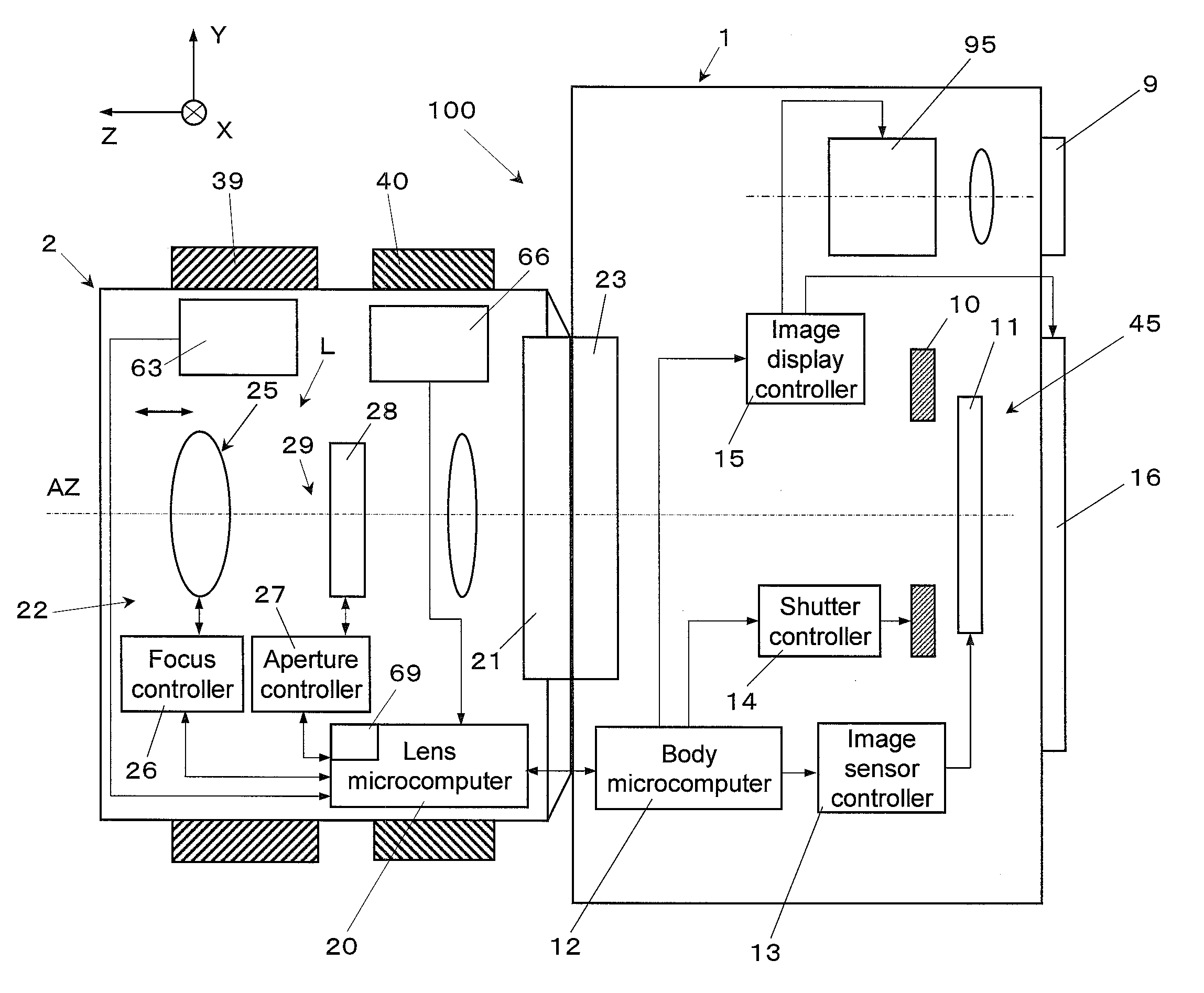
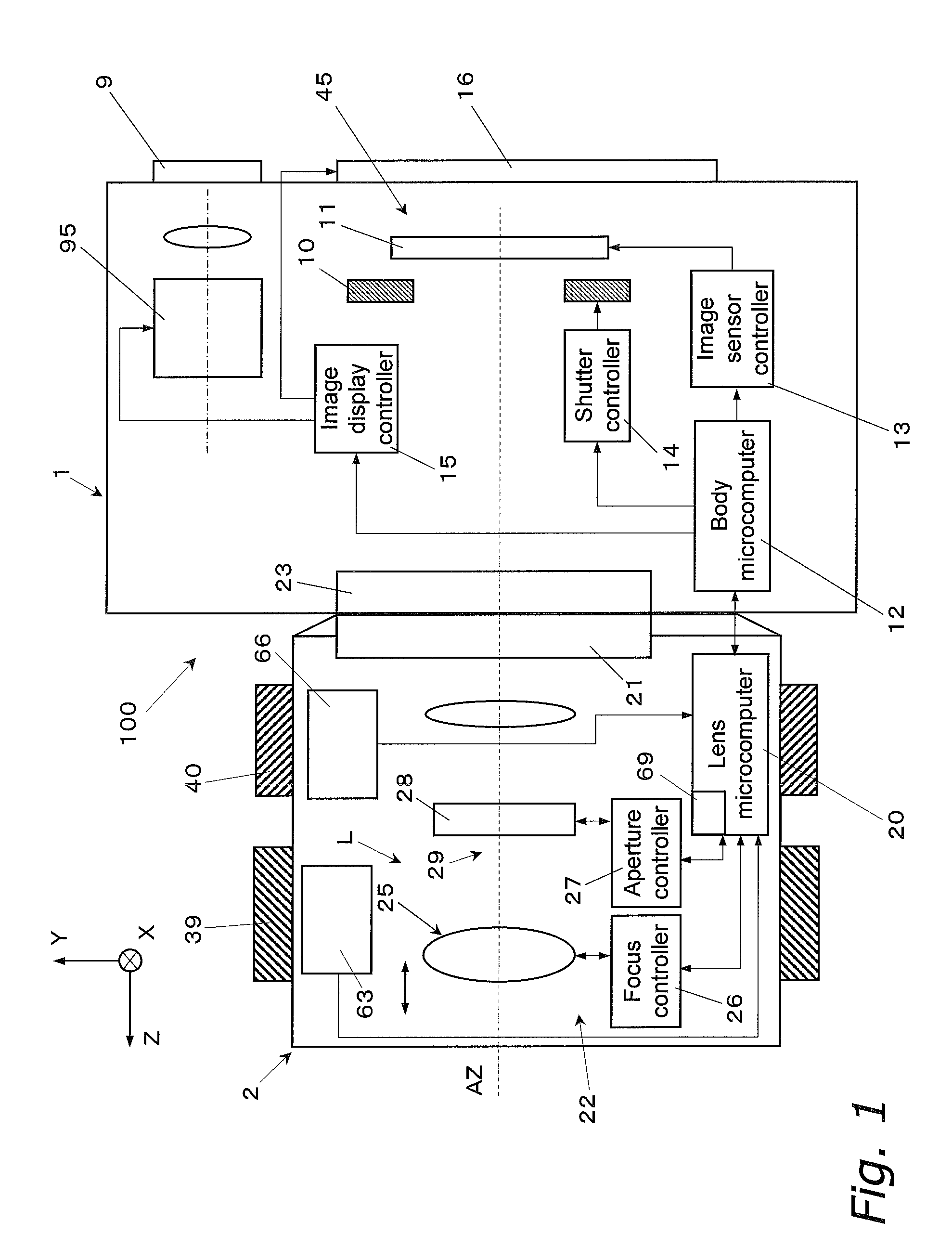
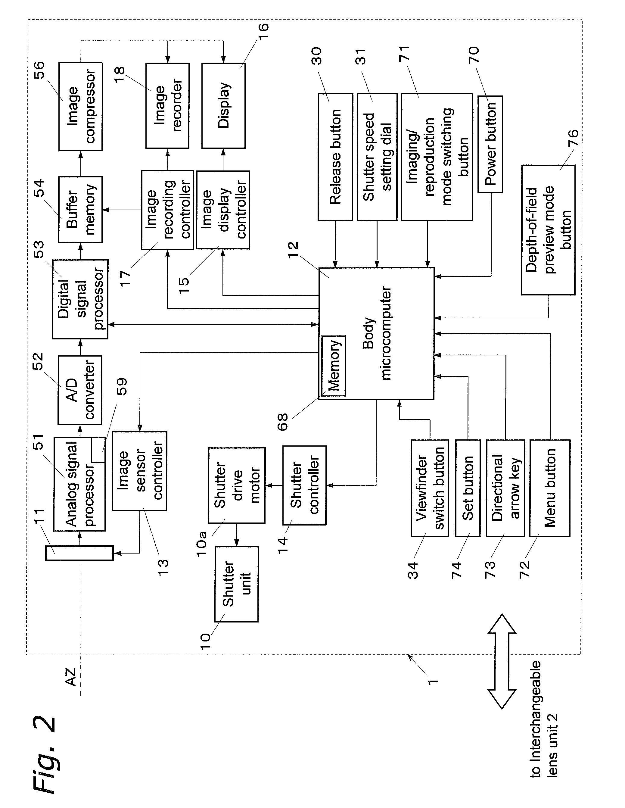
[0043]A digital camera 100 (an example of an imaging device) will be described as a first embodiment through reference to FIGS. 1 to 3. FIG. 1 is a diagram of the overall configuration of the digital camera 100. FIG. 2 is a control block diagram for a camera main body 1. FIG. 3 is a control block diagram for an interchangeable lens unit 2.

[0044]The digital camera 100 is an interchangeable lens type of single-reflex digital camera. The digital camera 100 mainly comprises the camera main body 1 and the interchangeable lens unit 2, which is removably mounted on the camera main body 1. The interchangeable lens unit 2 forms an optical image of a subject. The camera main body 1 converts an optical image formed by the interchangeable lens unit 2 into an image signal, and records image data, displays images, and so forth.

[0045]1.1: Interchangeable Lens Unit

[0046]As shown in FIGS. 1 and 3, the interchangeable lens unit 2 mainly comprises an opt...


PUM


Abstract

A digital camera has an optical system, an image capturing unit, an aperture adjuster, a focal point adjuster, and a body microcomputer. The aperture adjuster has an aperture included in the optical system and is capable of adjusting the state of the aperture. The focal point adjuster has a focus lens included in the optical system and is capable adjusting the focal state of the optical system by using the focus lens by contrast detection method. The body microcomputer controls the operation of the aperture adjuster so that the aperture value of the optical system will be at or below a set aperture value before the focal state is adjusted by the focal point adjuster.

Description

CROSS-REFERENCE TO RELATED APPLICATIONS[0001]This application claims priority to Japanese Patent Application No. JP 2008-103190 filed on Apr. 11, 2008. The entire disclosure of Japanese Patent Application No. JP 2008-103190 is hereby incorporated herein by reference.BACKGROUND[0002]1. Technical Field[0003]The technical field relates to an imaging device, and more particularly to an image capturing unit having an aperture value update function.[0004]2. Description of the Related Art[0005]Digital cameras and other such imaging devices have exploded in popularity in recent years. One type of digital camera is the digital single lens reflex camera. When a subject is viewed through the optical viewfinder of this digital single lens reflex camera, the light incident on the optical system (that is, the subject image) is reflected by a reflecting mirror disposed along the optical path, and is guided to the viewfinder optical system. As a result, the subject image is converted by a pentapris...

Claims


Application Information

Patent Timeline
Patent Type & Authority Patents(United States)
IPC IPC(8): G03B13/00G03B3/00G03B7/00H04N5/238G02B7/28G02B7/36G03B13/36H04N5/232
CPCG03B13/30G03B13/36G03B17/14G03B17/20H04N5/23212H04N23/959H04N23/673H04N23/635
Inventor YUMIKI, NAOTO
Owner PANASONIC INTELLECTUAL PROPERTY CORP OF AMERICA
Learn More