
Radiant baffle/collector for roof construction and retrofit

a technology for collecting and roofs, applied in the field of baffle systems, can solve the problems of increasing the cost of construction, and high cost of thick structures

Active Publication Date: 2012-03-20
KLEMENT MICHAEL ROBERT
View PDF26 Cites 20 Cited by
  • Summary
  • Abstract
  • Description
  • Claims
  • Application Information

AI Technical Summary

Benefits of technology

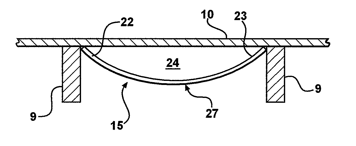
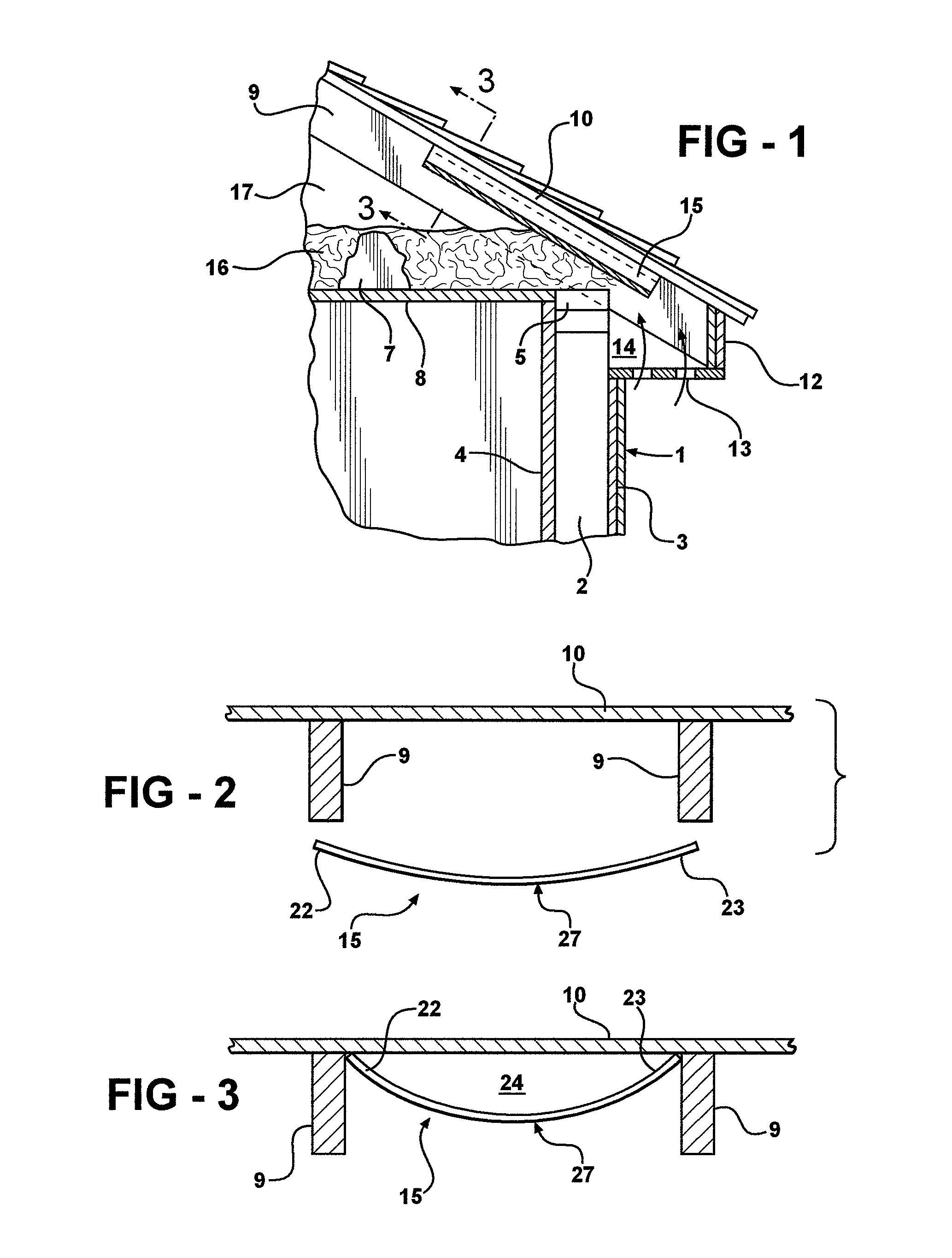
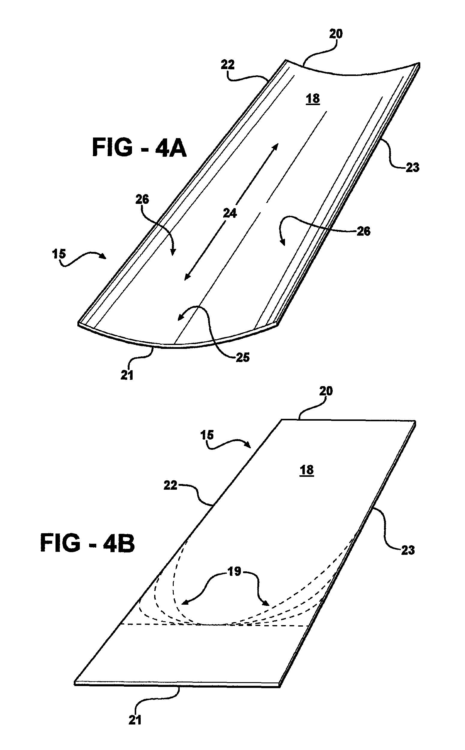
"The present invention provides a baffle vent for roofs that helps to direct air from a soffit area to the roof upwardly over the interior surface of the roof. The baffle vent is made of a flexible, curved sheet-like material that can be easily bent and positioned between adjacent rafters to hold it in place. The invention also includes a method for installing the baffle vent and a radiant collector system that includes solar thermal collectors and a grid for coupling to the collectors. The technical effects of the invention include improved ventilation, better air flow, and improved energy efficiency in roof constructions."

Problems solved by technology

A major consideration in the design and manufacture of such baffle vents has been the cost of such structures.
Such thick structures were relatively expensive and added appreciably to the cost of construction.
It readily can be understood that baffle vent structures that are designed for attaching to the interior surface of the roof sheeting, are not suitable for use when the ceiling / roof structure is manufactured inside-out as described above.

Method used


Image

  • Radiant baffle/collector for roof construction and retrofit
  • Radiant baffle/collector for roof construction and retrofit
  • Radiant baffle/collector for roof construction and retrofit

Examples


Embodiment Construction

[0040]The present invention relates to the ventilation of attics and cathedral ceilings and to controlling the transfer of heat energy between the roof surface and the structure below, e.g. attic space or cathedral ceiling. More particularly, the present invention relates to a baffle system that can be used to provide ventilation to attics and roofs at the time of new roof construction or retrofit. The present invention further provides for the reduction of radiant heat transfer from the roof surface inward toward the structure below, including the attic and living space that might be air conditioned in the summer, and also provides for the reduction of heat transfer from the living space and / or attic outward toward the roof surface in the winter. In addition, the present invention provides for the harvesting of solar thermal energy for solar heating systems, such as but not limited to, domestic water heating, in conjunction or in combination with the baffle systems.

[0041]According ...


PUM


Abstract

A baffle system that can be used to provide ventilation to attics and roofs at the time of new roof construction or retrofit and further provides for solar thermal energy control and harvesting systems in conjunction or combination with the baffle systems. According to one embodiment, the baffle vents are made from a resilient material and are designed and configured to be flexed into a deformed shape, positioned between adjacent roof rafters and released whereupon the baffle vents become wedged between adjacent roof rafters. According to another embodiment the baffle vents have side edge portions that are configured to extend over the upper portions of roof rafters and thereby support the baffle vents between adjacent roof rafters. The baffle vents can function as radiant barriers by providing the baffle vents with a reflecting coating(s) or reflective surface(s). The baffle vents can function as radiant collectors by positioning solar thermal collectors in the air flow channels defined by the baffle vents and darkening the lower surface of the roof sheeting plane. Stock baffle vents are configured to provide for insulation dams that can be cut from the ends of the baffle vents.

Description

TECHNICAL FIELD[0001]The present invention relates to the ventilation of attics and roof undersides. More particularly, the present invention relates to a baffle system that can be used to provide ventilation to attics and roofs at the time of new roof construction or retrofit and further provides for solar energy control and harvesting systems in conjunction or combination with the baffle systems.BACKGROUND ART[0002]It has been known to provide various forms of baffles in roofing structures to direct or channel air along the underside of the roof, usually from the soffit area of the roof upwardly into an attic space or toward vent ducts or a crest or ridge vent. Such baffle vents often are referred to as “vent chutes.” The baffle vents provide barriers to separate the interior surface of the roof from the attic area and from such extraneous materials such as insulation which might be located near the underside of the roof. The baffles direct the air against the under surface of the...

Claims


Application Information

Patent Timeline
Patent Type & Authority Patents(United States)
IPC IPC(8): E04D13/18
CPCE04D13/178F24J2/045F24J2/14F24J2/26F24J2/52Y02B10/20Y02E10/44Y02E10/45Y02E10/47F24S25/00F24S20/67F24S23/74F24S10/75Y02E10/40
Inventor KLEMENT, MICHAEL ROBERT
Owner KLEMENT MICHAEL ROBERT
Learn More