
Pivot pin with gripper feature

a technology of pivoting pins and hinges, which is applied in the direction of hinges, wing accessories, manufacturing tools, etc., can solve the problems of low energy efficiency, low stress concentration in the panel, and a dangerous situation for a pet left outdoors, so as to reduce stress concentration and not deform.

Active Publication Date: 2012-03-20
AMBROSE JOSEPH V
View PDF16 Cites 4 Cited by
  • Summary
  • Abstract
  • Description
  • Claims
  • Application Information

AI Technical Summary

Benefits of technology

"The present disclosure is about a swinging door hinge that reduces stress concentrations and deformation of the panel. The hinge has a pivot pin that is vertically disposed through an aperture in the frame, and a gripper feature on the pivot pin that engages a corresponding surface on the panel. This results in a torsional force transferred to the pivot pin that is spread over a contact area between the gripper feature and the panel surface. The hinge can also include a torsional spring that biases the panel into a position that is parallel to the frame. The gripper feature can be a teeth arrangement or an adhesive material. The hinge can also have a well defined in the panel that receives a portion of the pivot pin. These features help to prevent deformation of the panel and reduce stress concentrations."

Problems solved by technology

However, in most climates, temperature variations from day to day could present a hazardous situation for a pet left outdoors.
While accomplishing the function of giving the pet access in and out of the home, these early “doggy doors” did not seal well and thus were very energy inefficient.
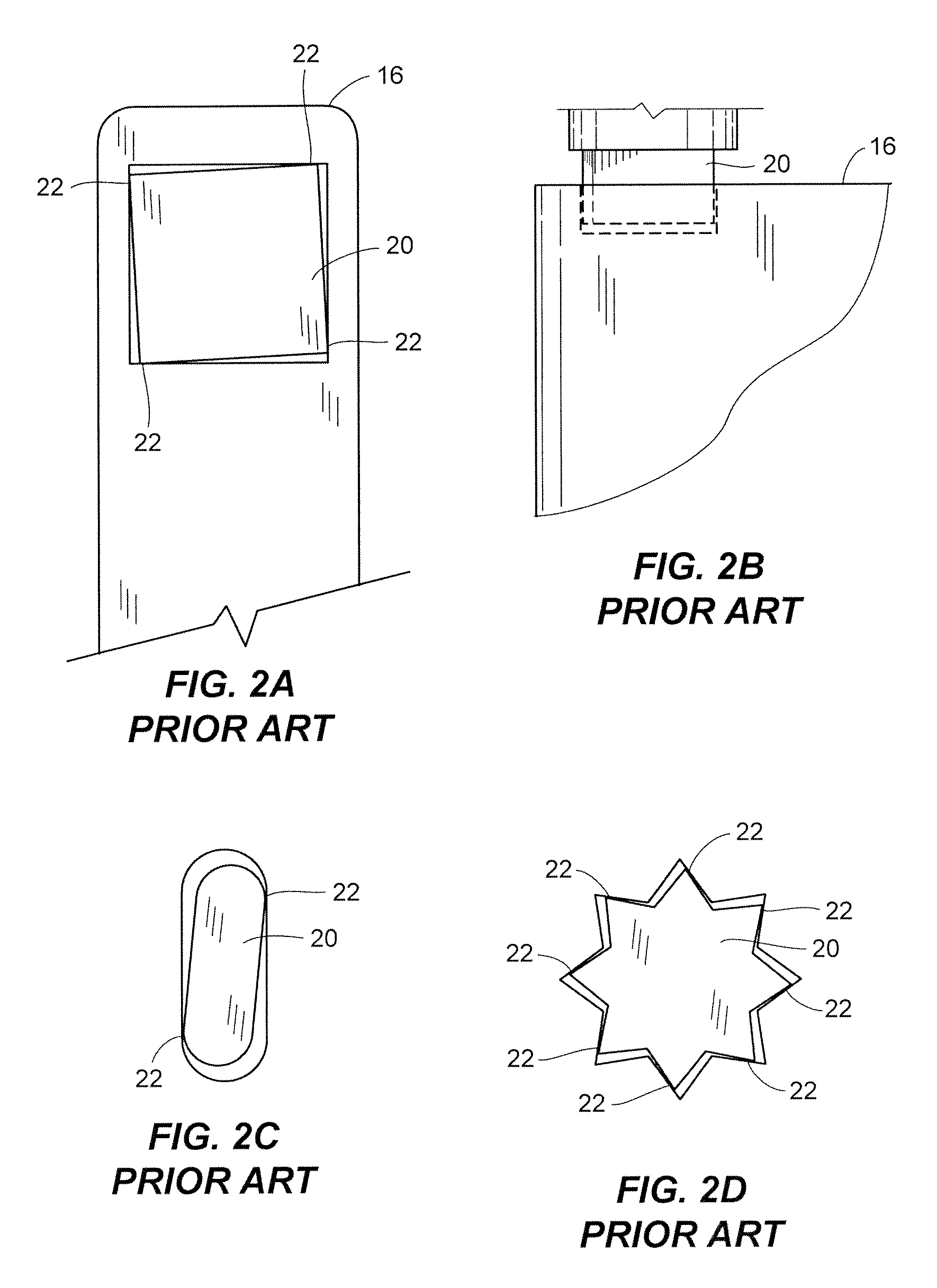
As a result, most prior art panels 16 eventually fail in the vicinity of the contact points 22 due to the repeated focused force from a pet pushing open the panel 16.
Replacement of the damaged panel 16 or pivot pin 20 is expensive, time consuming, and physically difficult.

Method used


Image

  • Pivot pin with gripper feature
  • Pivot pin with gripper feature
  • Pivot pin with gripper feature

Examples


Embodiment Construction

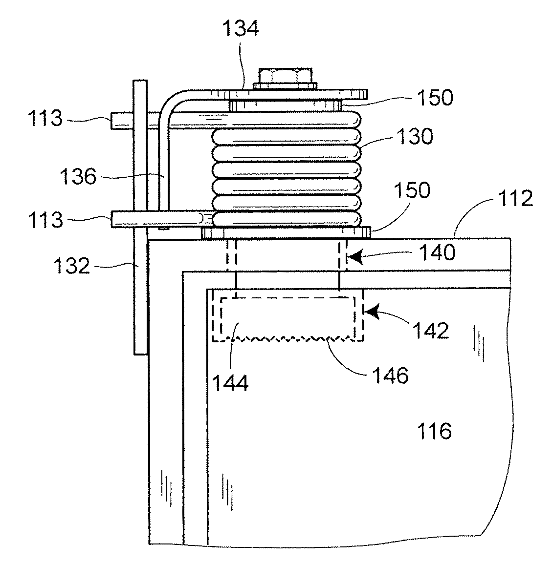
[0029]Turning now to FIG. 3A, a pivot pin 120 is shown mounted in a panel 116 of a pet door, for example. The pivot pin 120 centrally locates a torsional spring 130, the ends 113 of which are restrained by a vertical plate 132 that is mounted to a vertical portion of a frame 112. A bent arm 134 is attached to the end of the pivot pin 120 by a fastener 138. The bent arm 134 axially retains the spring 130 and provides a lever arm 136 that is centered between the ends 113 of the spring 130 and transforms angular displacement of the panel 116 to spring energy. The spring energy is then used to close the panel 116 in either direction after a pet exits the opening. The pivot pin 120, the spring 130, and the bent arm 134 are fastened to the panel 116 by the fastener 138 in a manner that will be described. The pivot pin 120 extends through an aperture 140 on a horizontal portion of the frame 112 and into a well 142 in the panel 116. The well 142 of this embodiment has a greater diameter tha...


PUM


Abstract

A swinging door hinge has a panel and a frame. The frame includes a horizontal portion, and the horizontal portion has an aperture therethrough. An elongated pivot pin is vertically disposed through the aperture. The pivot pin is coupled to the panel such that the pivot pin and the panel rotate about a longitudinal axis of the pivot pin relative to the horizontal portion of the frame. A gripper feature is located on a surface of the pivot pin. The gripper feature engages a corresponding surface on the panel such that when the panel is rotated, a resulting torsional force transferred to the pivot pin is spread over contact area between the gripper feature and the surface of the panel. Because the torque is transferred over a greater area, stress concentrations in the panel are reduced and the panel is not deformed.

Description

CROSS REFERENCE TO RELATED APPLICATIONS[0001]The priority benefit of U.S. Provisional Application No. 60 / 988,632 filed Nov. 16, 2007 is claimed, and the entire contents thereof are expressly incorporated herein by reference.FIELD OF THE INVENTION[0002]The disclosure relates generally to pivot pins for swinging doors and specifically to pivot pins for swinging pet doors.BACKGROUND OF THE INVENTION[0003]Pets are an integral part of many families. Dogs and cats are by far the most popular types of pets. Dogs and cats, like all animals, occasionally require access to the outdoors for exercise or to perform other biological functions. Traditionally, owners of pets opened a full size door each time the pet wanted to go outdoors and walked the pet on a leash. Eventually, some owners began fencing a portion of land so that the pet would be free to run within a confined space. Some owners found it convenient to leave the pet in the fenced in portion for most of the day, thereby avoiding repe...

Claims


Application Information

Patent Timeline
Patent Type & Authority Patents(United States)
IPC IPC(8): E05D5/10
CPCE05D3/08E05F1/1215E06B7/32E05D7/081E05D15/54E05Y2900/132Y10T16/538Y10T16/557Y10T16/539Y10T16/53828Y10T16/5445Y10T16/599Y10T16/5389
Inventor AMBROSE, JOSEPH V.
Owner AMBROSE JOSEPH V
Learn More