
Virtualization system with hypervisor embedded in bios or using extensible firmware interface

a virtualization system and bios technology, applied in the field of virtualization, can solve the problems of operating system not being able to recover from this situation, code remains unsecured, and no way of knowing

Active Publication Date: 2012-02-28
PARALLELS INT GMBH
View PDF4 Cites 91 Cited by
  • Summary
  • Abstract
  • Description
  • Claims
  • Application Information

AI Technical Summary

Benefits of technology

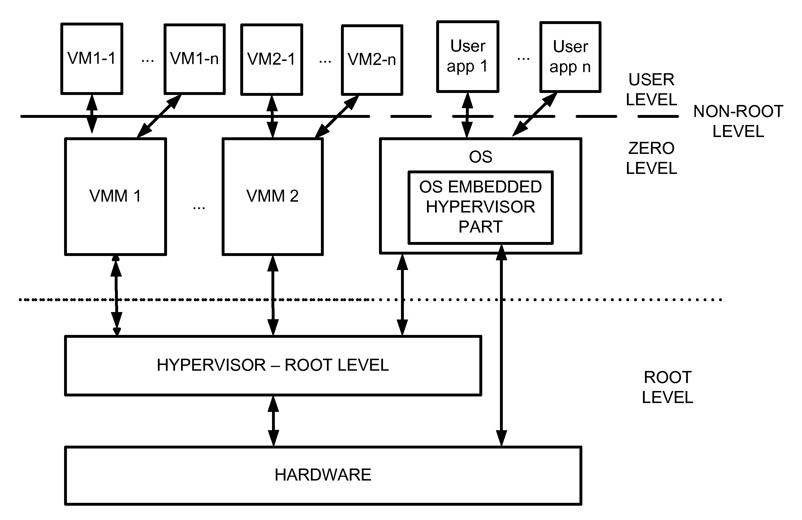
[0030]FIG. 4 illustrates an exemplary embodiment of the invention where the Hypervisor is a part of the EFI-module for the EFI loading during platform initialization stage and is moved to root mode before operating system start, and the OS boots in non-root mode under Hypervisor control.

Problems solved by technology

A frequent situation that arises in this context is the problem of emulating (or, more broadly, virtualizing) a different operating system on the same processor.
Disadvantage is in that code is still remaining unsecured because some kind of kernel extension can be a blue pill (see further description) especially if this extension starts before VMWare's hypervisor.
An additional problem is many of the current operating systems are due to the fact that modern microprocessors, such as Intel and any AMD microprocessors, include support for virtualization on a hardware level.
Once this happens, the operating system has no way of recovering from this situation, and no way of knowing that this has occurred, if the virus is sufficiently “smart” to fool the operating system into thinking that it (meaning, the OS) is still running on the root level.

Method used


Image

  • Virtualization system with hypervisor embedded in bios or using extensible firmware interface
  • Virtualization system with hypervisor embedded in bios or using extensible firmware interface
  • Virtualization system with hypervisor embedded in bios or using extensible firmware interface

Examples


Embodiment Construction

[0031]Reference will now be made in detail to the embodiments of the present invention, examples of which are illustrated in the accompanying drawings.

[0032]The approach described herein takes advantage of newer architectures for loading the code relating to the basic functions of the computer into memory. Earlier microprocessor-based systems used so-called BIOS (basic input / output system), which was typically embedded into a read-only flash memory (although some special utilities are available that can update the BIOS), and located at an address that would be accessed by the microprocessor upon startup. Typically, the BIOS is a fairly primitive operating system, essentially, it loads the minimum drivers needed for the computer to become functional (for example, to talk to the keyboard, the disk drive, the monitor, and so on), and then its job is to call an operating system loader, which then loads the operating system, such as Microsoft Windows, into memory.

[0033]A more modern solu...


PUM


Abstract

A computer system includes a first portion of a Hypervisor is loaded into the memory as a part of an Extensible Firmware Interface upon start up and prior to loading of an operating system. The first portion is responsible for context switching, at least some interrupt handling, and memory protection fault handling. The first portion runs on a root level. An operating system is loaded into a highest privilege level. A second portion of the Hypervisor is loaded into operating system space together with the operating system, and runs on the highest privilege level, and is responsible for (a) servicing the VMM, (b) servicing the VMs, (c) enabling communication between code launched on non-root level with the second portion of the Hypervisor to perform security checks of trusted code portions and to enable root mode for the code portions if allowable. The VMM runs on the highest privilege level. A Virtual Machine is running under control of the VMM. Trusted code runs on non-root level. The first portion of the Hypervisor verifies trusted code portions during their loading or launch time, and the trusted code is executed on root level.

Description

BACKGROUND OF THE INVENTION[0001]1. Field of the Invention[0002]The present invention relates to virtualization, and more particularly, to hypervisor-based virtualization systems.[0003]2. Background Art[0004]With Virtual Machine (VM) technology, a user can create and run multiple operating environments on a server at the same time. Each operating environment, or Virtual Machine, requires its own operating system (OS) and can run applications independently. The VM software provides a layer between the computing, storage, and networking hardware and the software that runs on it.[0005]Virtual Machine technology can lower information technology (IT) cost through increased efficiency, flexibility, and responsiveness. Each VM acts as a separate environment, which reduces risk and allows developers to quickly re-create different operating system (OS) configurations or compare versions of applications designed for different OS's. Additional customer uses for VMs include targeted production ...

Claims


Application Information

Patent Timeline
Patent Type & Authority Patents(United States)
IPC IPC(8): G06F9/455G06F9/445
CPCG06F9/45541G06F9/45558G06F2009/45587G06F21/30
Inventor DOBROVOLSKIY, NIKOLAY N.TORMASOV, ALEXANDER G.KORYAKIN, ALEXEY B.
Owner PARALLELS INT GMBH
Learn More