Method and device for cavity enhanced optical vernier spectroscopy

a technology of enhanced optical vernier and cavity, applied in the direction of optical radiation measurement, instruments, spectrometry/spectrophotometry/monochromators, etc., can solve the problems of limited resolution of conventional ceas methods, inability to resolve individual comb components of light pulse trains coupled into the resonator cavity, and inability to solve the individual comb components of light pulse trains. , to achieve the effect of boosting the resolution of the method, enhancing the transmission frequency spacing, and boosting the absorption spectrum

Inactive Publication Date: 2012-02-21
MAX PLANCK GESELLSCHAFT ZUR FOERDERUNG DER WISSENSCHAFTEN EV
View PDF2 Cites 7 Cited by
  • Summary
  • Abstract
  • Description
  • Claims
  • Application Information

AI Technical Summary

Benefits of technology

[0009]According to a first aspect of the invention, the above objective is solved by providing a cavity enhanced absorption spectroscopy method wherein due to a detuning of a source frequency spacing characteristic for a frequency comb of pulsed source light and a cavity mode frequency spacing characteristic for a mode comb of a resonator cavity, light pulses transmitted by the resonator cavity have an enlarged transmitted frequency spacing. With the enlarged transmitted frequency spacing, single frequency components of the pulsed light can be spectrally resolved. Advantageously, individual source comb components can be resolved so that the method of the invention can boost the resolution of the method from the limitation of usual spectral disperser techniques to the Hertz level that is provided e.g. by stabilized laser sources.
[0010]According to a second aspect of the invention, the above objective is solved by providing a spectroscopic device, being adapted in particular for cavity enhanced absorption analysis of a sample, wherein a pulse source device and a resonator cavity being arranged for providing the source frequency spacing and the cavity mode frequency spacing detuned relative to each other, so that the transmitted light comprises a transmitted frequency spacing larger than the source frequency spacing. In particular, the spectroscopic device is configured for implementing the method according to the above first aspect. Advantageously, the invention provides a simple yet powerful device that yields broad band high resolution spectra for both absorption and dispersion of a sample placed between mirrors of the resonator cavity.
[0011]An essential feature of the invention is the detuning of the source frequency spacing and the cavity mode frequency spacing, which results in a transmission of certain source frequencies through the resonator cavity only. A detuning ratio of both frequency spacings determines, which of the cavity mode frequencies are matched to source frequencies. Accordingly, the detuning ratio determines the source frequencies exclusively transmitted by the resonator cavity. Detuning of the frequency spacings results in a suppression of transmitted light corresponding to a large number of cavity mode frequencies. The transmitted light is represented by a frequency comb having a transmitted frequency spacing, which is enlarged compared with the source frequency spacing in a predetermined manner. Accordingly, detuning of the frequency spacings results in a frequency filtering effect of the resonator cavity. Transmitted light having transmitted comb frequencies (resonant cavity mode frequencies with enlarged transmitted frequency spacing) can be detected with spectral resolution using a spectral disperser, wherein any unintended contributions of other source frequencies is avoided. In particular, individual comb frequencies of the transmitted light can be detected and resolved in first order diffraction of the spectral disperser or with refraction using a dispersive prism.

Problems solved by technology

The conventional CEAS methods have a disadvantage as the resolution of these methods is limited by the spectrometer, recording the ring down signal and ignoring the high temporal coherence of the driving signal.
In particular, with the conventional CEAS methods it is impossible to resolve the individual comb components of a light pulse train coupled into the resonator cavity.
Combining high sensitivity of the conventional CEAS method of M. J. Thorpe et al. with high spectral resolution in an efficient and unambiguous manner proves challenging.
Therefore it is difficult to distinguish between a reduction in transmission due to dispersion or due to absorption.
However, both of the latter techniques are not capable to detect the comb components with sufficient spectral resolution.

Method used


Image

  • Method and device for cavity enhanced optical vernier spectroscopy
  • Method and device for cavity enhanced optical vernier spectroscopy
  • Method and device for cavity enhanced optical vernier spectroscopy

Examples


Embodiment Construction

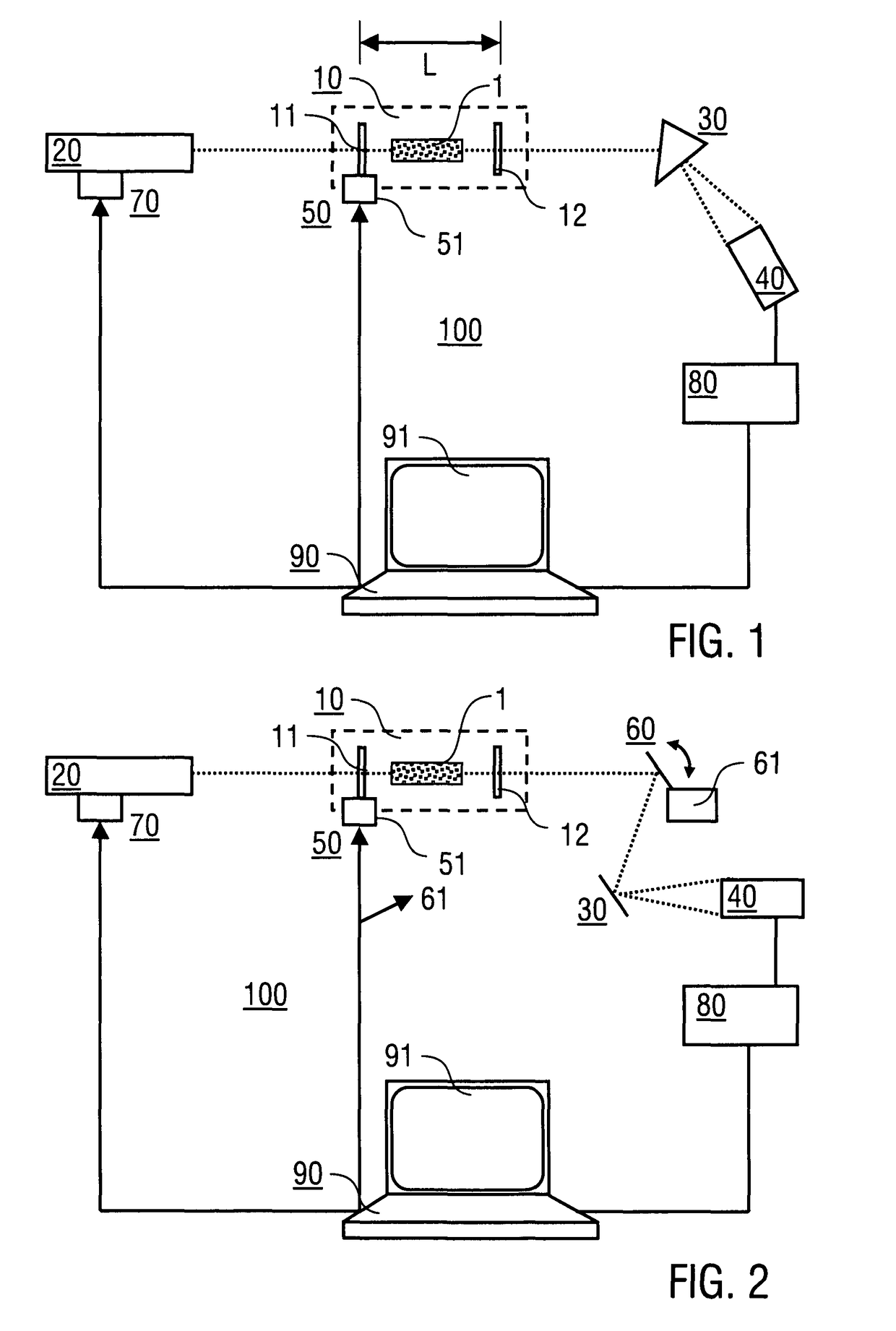
[0038]Preferred embodiments of the invention are illustrated in FIGS. 1 and 2. It is emphasized that these Figures represent schematic illustrations only. Details of the optical set-up, like e.g. controlling, driving or monitoring components or further optical parts are not described as far as they are known from prior art techniques of generating and handling ultra-short light pulses.

[0039]According to FIG. 1, the spectroscopic device 100 of the invention comprises a resonator cavity 10, a pulse source device 20, a spectral disperser device 30, a detector device 40, an adjusting device 50, a detuning device 70, an evaluation device 80 and a control device 90. The resonator cavity 10 comprises e.g. four mirrors in a bowtie ring cavity design, wherein only two mirrors 11, 12 are shown in FIG. 1. The mirrors 11, 12 are plane mirrors having a nominal trans-mission of 0.1% corresponding to a resonator finesse of 1000π (assuming negligible loss otherwise). The sample 1 comprises e.g. a g...


PUM


Abstract

A spectroscopic analysis of a sample includes arranging the sample in a resonator cavity for transmitting cavity mode frequencies with a cavity mode frequency spacing, coupling pulsed source light into the resonator cavity, with the source light including source comb frequencies with a source frequency spacing, coupling pulsed transmitted light out of the resonator cavity, and spectrally resolved detecting the transmitted light with a detector device. The cavity mode frequency spacing and the source frequency spacing are detuned relative to each other, so that the transmitted light includes transmitted comb frequencies with a spacing larger than the source frequency spacing. The detecting feature includes collecting spectral distributions of the transmitted light in dependence on relative positions of the cavity mode frequencies and the source comb frequencies. The cavity mode frequencies and the source comb frequencies are varied relative to each other and different transmitted comb frequencies are individually resolved.

Description

BACKGROUND OF THE INVENTION[0001]The present invention is related to a method of broad band high resolution spectroscopic analysis of a sample and to a spectroscopic device being adapted for implementing the method.[0002]The frequency spectrum of a periodic sequence of ultra-short light pulses consists of a regular arrangement of sharp lines (so-called frequency comb). Generally, the frequency width of the spectrum will be inversely proportional to the temporal width of the pulse envelope. Accordingly, a periodic sequence of femtosecond pulses is characterized by broadband frequency combs. The femtosecond frequency comb (see e.g. J. Reichert et al. in “Physical Review Letters” vol. 84, 2000, p. 3232, and S. T. Cundiff et al. in “Reviews of Moderns Physics” vol. 75, 2003, p. 325) has served as a universal optical clockwork mechanism (S. A. Diddams et al. in “Science” vol. 293, 2001, p. 825), has enabled new precision test of fundamental theories (M. Fischer et al. in “Physical Review...

Claims


Application Information

Patent Timeline
Patent Type & Authority Patents(United States)
IPC IPC(8): G01J3/28
CPCG01J3/10G01J3/26G01J3/433G01J3/457
Inventor GOHLE, CHRISTOPHSCHLIESSER, ALBERTHAENSCH, THEODOR W.
Owner MAX PLANCK GESELLSCHAFT ZUR FOERDERUNG DER WISSENSCHAFTEN EV
Why Eureka
Try Eureka