
Magnetic resonance imaging apparatus and radio frequency pulse waveform generating method

a magnetic resonance imaging and radio frequency pulse waveform technology, applied in the field of magnetic resonance imaging apparatus, can solve the problems of brightness inhomogeneity becoming more serious, the specific absorption rate of imaging sequences safely usable with a magnetic field of 1.5 tesla cannot be increased, and the imaging sequence safely usable with a magnetic field of 1.5 tesla cannot be used with a magnetic field of 3 tesla. , to achieve the effect of less sar and increase in sar

Inactive Publication Date: 2012-02-14
HITACHI LTD
View PDF17 Cites 11 Cited by
  • Summary
  • Abstract
  • Description
  • Claims
  • Application Information

AI Technical Summary

Benefits of technology

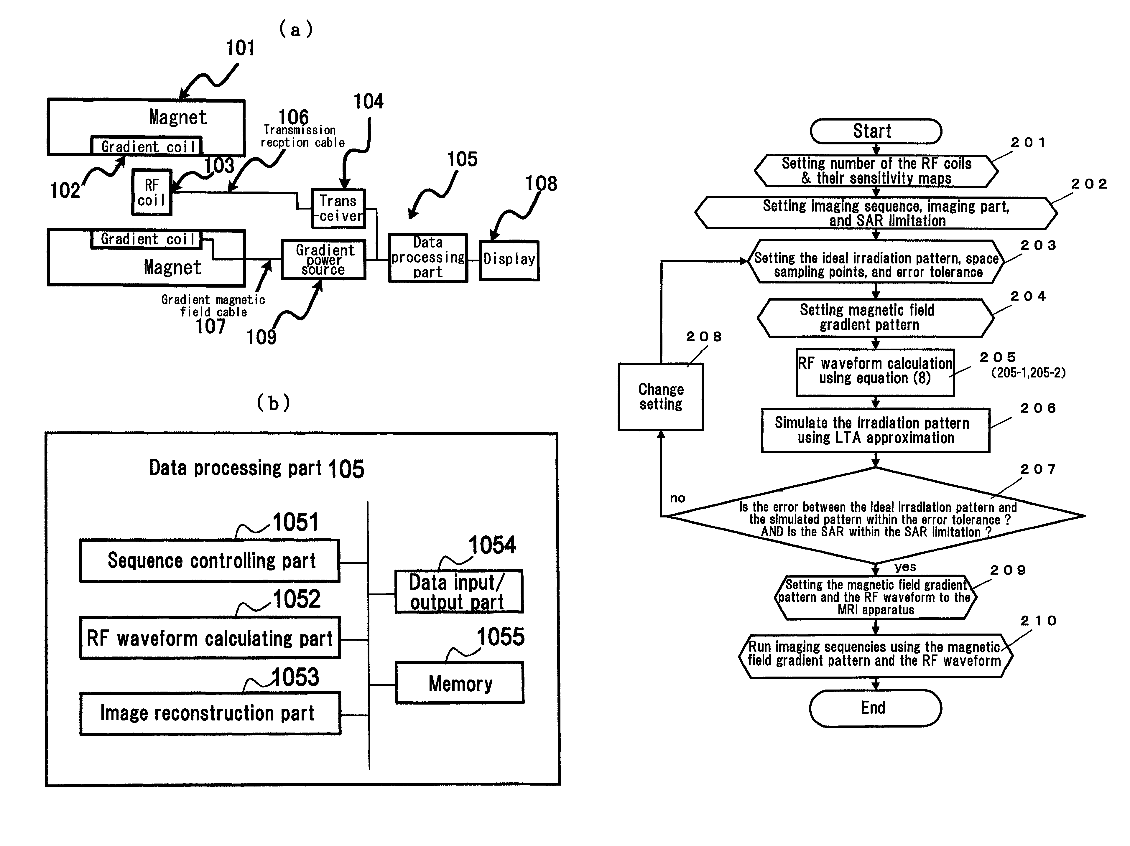
[0013]An object of the present invention is to correctly reproduce a predetermined irradiation pattern and reduce SAR in an MRI apparatus and thereby provide an MRI apparatus which can provide an image with less brightness inhomogeneity at a low SAR. Another object of the present invention is to provide a method for generating RF pulse waveform which makes it possible to obtain a radio frequency pulse (henceforth referred to as RF pulse) waveform showing a reduced SAR compared with that obtainable by conventional methods in processes of reproducing a correcting irradiation pattern with a calculated RF pulse waveform.
[0019]If a phase term of irradiation pattern is incorporated into the equation for minimization and imaging is performed by using the RF pulse, an RF waveform giving a less SAR than that obtainable by conventional methods can be obtained. This make it possible to use more various kinds of imaging methods compared with a case using conventional techniques even in an MRI apparatus using a magnetic field of 3 tesla or more which suffers from the problem of increase in SAR.

Problems solved by technology

As a result, in propagation of electromagnetic waves in human bodies, wave characteristics become significant, and specifically, inhomogeneity is generated in images obtained by MRI apparatuses.
The problem of brightness inhomogeneity becomes more serious especially when abdominal part of human body is imaged.
Ultrahigh magnetic field MRI apparatuses using a magnetic field of 3 tesla or more also have a problem of increase in SAR (specific absorption rate) due to the use of RF electromagnetic waves in addition to the problem of brightness inhomogeneity.
Therefore, there is a problem that an imaging sequence safely usable with a magnetic field of 1.5 tesla may not be used with a magnetic field of 3 tesla.
Moreover, in order to correctly reproduce the irradiation pattern, it is necessary to superimpose a moiety where electromagnetic waves are weakened by the gradient magnetic field and a moiety where electromagnetic waves are strengthened by the gradient magnetic field, and therefore the method has a problem of increase of SAR in principle.
However, such attempt has problems that (1) calculation of RF waveform and gradient magnetic field waveform becomes complicated, (2) since period of pulse irradiation becomes longer, error of irradiation pattern increases, and so forth.
In this method, since there is no restriction for the phase portion at all, the solution which should be calculated in minimization becomes unstable, and therefore the method has a serious drawback that a special method is required for calculation.

Method used


Image

  • Magnetic resonance imaging apparatus and radio frequency pulse waveform generating method
  • Magnetic resonance imaging apparatus and radio frequency pulse waveform generating method
  • Magnetic resonance imaging apparatus and radio frequency pulse waveform generating method

Examples


example 1

1. Determination of Preconditions

[0075]Supposing excitation of a cylindrical shape having a diameter of 10 cm using a coil having uniform sensitivity profile, such a cylindrical shape having a diameter of 10 cm as shown in FIG. 4 was defined as an ideal irradiation pattern m.

[0076]Further, the space sampling vector r in the equation (1) was prepared in such a manner that sampling should be performed at 400 points in a spiral shape winding 10 times within a circular shape having a diameter of 20 cm. The flip angle in the cylinder was set to be 45°. As for the time sampling number of the RF waveform, sampling was performed at 100 points. The trajectory of K-space vector in the equation (9) (gradient magnetic field pattern) was a spiral trajectory winding 10 times from the outside of maximum wave number of 0.3 / cm to the inside. A diagonal unit matrix comprising 400×400 elements was used as the sensitivity matrix S with the premise of using a coil showing uniform sensitivity.

2. Calculat...

example 2

1. Preconditions

[0090]As an ideal irradiation pattern m, there was used a pattern for exciting such a cylinder having a diameter of 4 cm in which flip angle was 45° and a cylinder having a diameter of 6 cm adjacent to the foregoing cylinder in which flip angle was 30°, total two cylinders, as shown in FIG. 8, (a). The K-space was swept with a gradient magnetic field in a spiral shape winding 10 times, the maximum value of K was 0.5 / cm, and sampling was performed at 400 points as time sampling number, and 40×40=1600 points in a square having sides of 20 cm as space sampling number.

2. Calculation of RF Waveform and Evaluation

[0091]As in Example 1, RF waveforms were calculated by the conventional method and the method of the present invention, irradiation patterns were calculated from the calculated RF waveforms by using LTA approximation, and errors of the absolute values of the irradiation patterns (%), the values of SAR and phases of the irradiation patterns were compared. In the ca...


PUM


Abstract

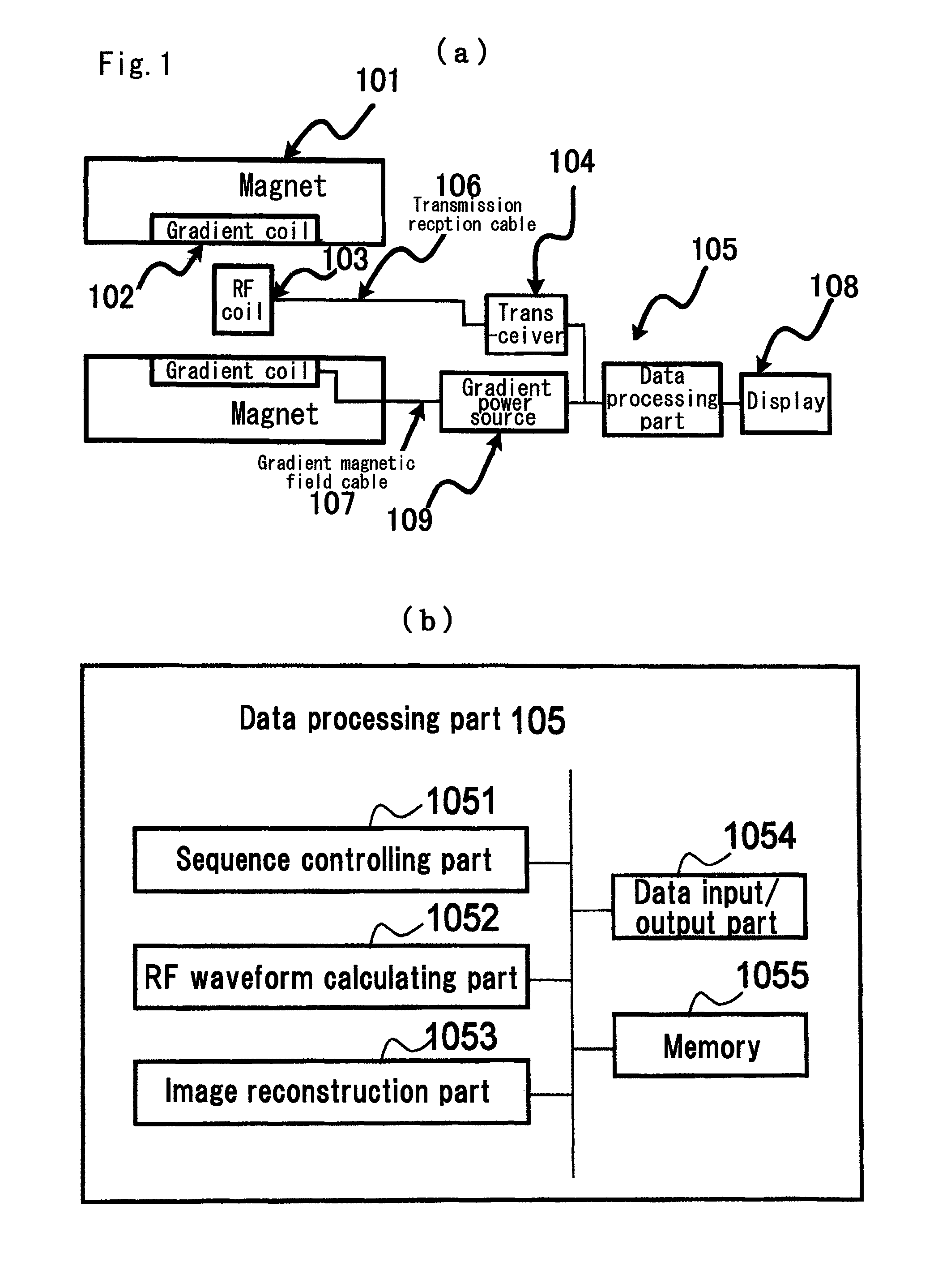
An MRI apparatus comprises a waveform controlling means for calculating a radio frequency pulse and applying the pulse to an irradiating means, and the waveform controlling means reads out a radio frequency pulse waveform vector from a first memory means which memorizes multiple radio frequency pulse waveform vectors, calculates a simulated irradiation pattern, and calculates a radio frequency pulse waveform which gives the minimum value of weighted sum of squares of differences of absolute values and squares of differences of phases for an ideal irradiation pattern and the simulated irradiation pattern. An RF pulse waveform showing superior ideal irradiation pattern reproducibility and providing reduced power of the RF waveform is formed, and safety of MRI subject is improved by performing imaging using such an RF pulse.

Description

CLAIM OF PRIORITY[0001]The present application claims priority from Japanese patent application JP 2007-281531 filed on Oct. 30, 2007, the content of which is hereby incorporated by reference into this application.TECHNICAL FIELD[0002]The present invention relates to a magnetic resonance imaging apparatus (henceforth referred to as MRI apparatus), and the present invention relates especially to a method for calculating a radio frequency pulse waveform for exciting a test subject.BACKGROUND ART[0003]An MRI apparatus generates images of a test subject by placing the test subject in a uniform static magnetic field generated by a magnet to irradiate electro magnetic waves to the test subject and excite nuclear spins in the test subject, and then receiving nuclear magnetic resonance signals as electromagnetic waves generated by the nuclear spins to visualize the test subject. The irradiation of the electromagnetic waves and reception of the nuclear magnetic resonance signals are performe...

Claims


Application Information

Patent Timeline
Patent Type & Authority Patents(United States)
IPC IPC(8): G01V3/00A61B5/055G06K9/00
CPCG01R33/288G01R33/3607G01R33/4833G01R33/4836
Inventor HABARA, HIDETABITO, YOSHITAKA
Owner HITACHI LTD
Learn More