
Gate driving circuit and display apparatus having the same

a driving circuit and display device technology, applied in electronic switching, digital storage, instruments, etc., can solve the problems of holding transistors that cannot hold gate voltage, gate driving circuits of prior art that cannot hold ripple components of gate voltage generated, etc., to achieve the effect of preventing ripple voltag

Active Publication Date: 2012-01-17
SAMSUNG DISPLAY CO LTD
View PDF3 Cites 11 Cited by
  • Summary
  • Abstract
  • Description
  • Claims
  • Application Information

AI Technical Summary

Benefits of technology

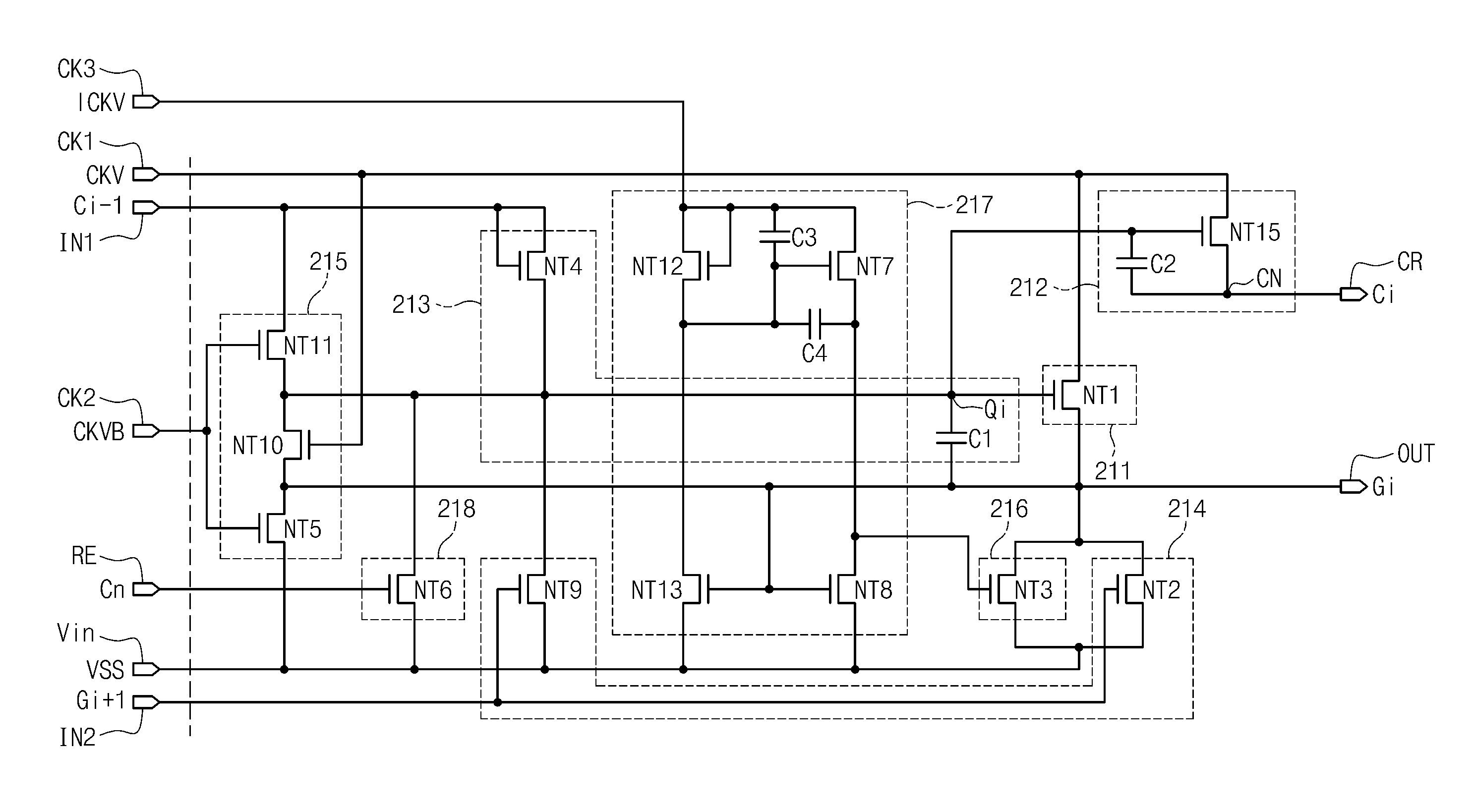
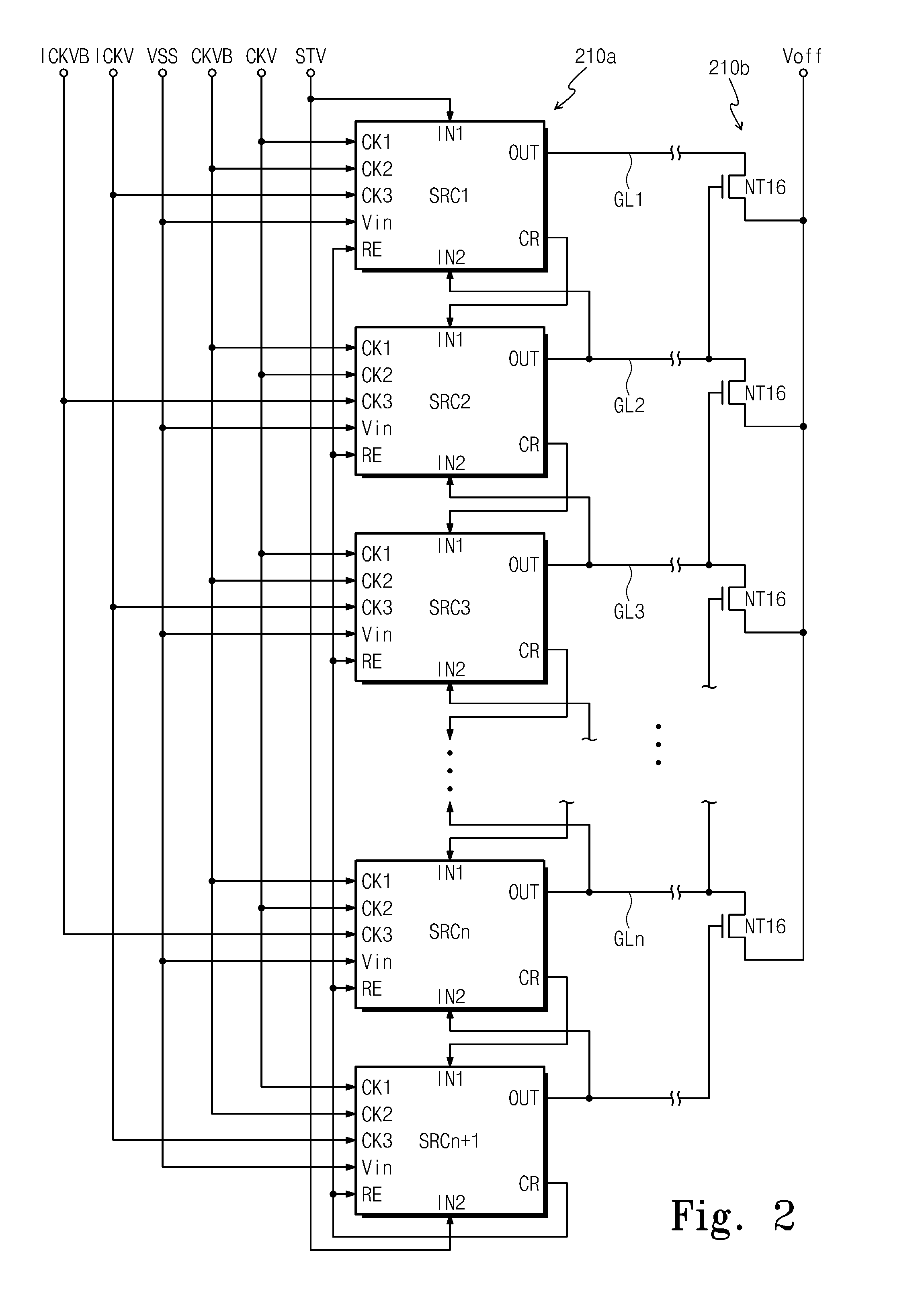
The present invention provides a gate driving circuit that prevents ripple in gate voltage and a display apparatus including the gate driving circuit. The gate driving circuit includes cascaded stages with a pull-up part, a carry part, a pull-up driving part, a holding part, and an inverter. The inverter controls the holding transistor based on an inverter clock that temporally precedes the input clock by a predetermined time interval. This prevents the output timing of the off-voltage from occurring after the transition timing of the input clock, reducing or effectively preventing ripple voltage. The technical effect of the invention is to improve the stability and reliability of the gate driving circuit.

Problems solved by technology

However, due to a signal delay, the holding transistor is not able to hold the gate voltage at the off-voltage level until after a signal delay time lapses after a time when the input clock is input to the inverter.
As a result, the gate driving circuit of the prior art is not able to hold the ripple component of the gate voltage generated at the transition time of the input clock at the off-voltage level.

Method used


Image

  • Gate driving circuit and display apparatus having the same
  • Gate driving circuit and display apparatus having the same
  • Gate driving circuit and display apparatus having the same

Examples


Embodiment Construction

[0033]The invention will now be described more fully hereinafter with reference to the accompanying drawings, in which exemplary embodiments of the invention are shown. The present invention may, however, be embodied in many different forms and should not be construed as limited to the embodiments set forth herein. Rather, these embodiments are provided so that this disclosure will be thorough and complete, and will fully convey the scope of the invention to those skilled in the art. Like reference numerals refer to like elements throughout.

[0034]It will be understood that when an element is referred to as being “on” another element, it can be directly on the other element or intervening elements may be present therebetween. In contrast, when an element is referred to as being “directly on” another element, there are no intervening elements present. As used herein, the term “and / or” includes any and all combinations of one or more of the associated listed items.

[0035]It will be unde...


PUM


Abstract

A gate driving circuit includes cascaded stages, each including a pull-up part, a carry part, a pull-up driving part, a holding part and an inverter. The pull-up part pulls up a gate voltage to an input clock. The carry part pulls up a carry voltage to the input clock. The pull-up driving part is connected to a control terminal (Q-node) common to the carry part and the pull-up part, and receives a previous carry voltage from a previous stage to turn on the pull-up part and the carry part. The holding part holds the gate voltage at an off-voltage, and the inverter controls at least one of turning on the holding part and turning off the holding part based on an inverter clock. A high level of the inverter clock in a given horizontal period (1H) temporally precedes a high level of the input clock by a predetermined time interval.

Description

[0001]This application claims priority to Korean Patent Application No. 2008-09212, filed on Jan. 29, 2008, and all the benefits accruing therefrom under 35 U.S.C. §119, the contents of which in its entirety are herein incorporated by reference.BACKGROUND OF THE INVENTION[0002]1. Field of the Invention[0003]The present invention relates to a gate driving circuit and a display apparatus including the gate driving circuit. More particularly, the present invention relates to a gate driving circuit having substantially improved output characteristics thereof, and a display apparatus including the gate driving circuit.[0004]2. Description of the Related Art[0005]In general, a liquid crystal display includes a liquid crystal display panel to display a desired image thereon. The liquid crystal display panel includes a lower substrate, an upper substrate facing the lower substrate and a liquid crystal layer interposed between the lower substrate and the upper substrate. The liquid crystal d...

Claims


Application Information

Patent Timeline
Patent Type & Authority Patents(United States)
IPC IPC(8): G09G3/36
CPCG09G3/3677G11C19/184H03K17/165G02F1/133G09G3/20G09G3/36G11C19/00
Inventor LEE, HONG-WOOLEE, JONG-HWANKIM, BEOM-JUNKIM, SUNG-MANKIM, GYU-TAEJANG, KYOUNG-JUN
Owner SAMSUNG DISPLAY CO LTD
Learn More