
Catalyst for reducing carbon monoxide concentration

a carbon monoxide and catalyst technology, can solve the problems of inability to avoid hydrogen loss, inability to meet the efficiency requirements, and the two-step method that is applied in the field of catalysts, and achieve the effect of improving the methanation capability of the catalys

Inactive Publication Date: 2012-01-10
NIPPON OIL CORP
View PDF17 Cites 3 Cited by
  • Summary
  • Abstract
  • Description
  • Claims
  • Application Information

AI Technical Summary

Benefits of technology

"The present invention is related to a catalyst and a method for reducing carbon monoxide concentration in a raw material gas containing hydrogen and carbon monoxide. The catalyst is designed to selectively oxidize carbon monoxide and methanate it to reduce the carbon monoxide concentration in the resulting product gas. By controlling the loading depth and concentration profile of ruthenium in the catalyst, the methanation capability of the catalyst is improved and the carbon monoxide concentration in the resulting product gas is efficiently reduced. The catalyst can be used in a fuel cell system to produce a hydrogen-rich gas as a fuel for the cathode."

Problems solved by technology

However, mere methanation of carbon monoxide causes loss of hydrogen that will be used as fuel for a fuel cell and thus is not appropriate in view of efficiency.
The aforesaid two-step method can not avoid loss of hydrogen at the first step.

Method used


Image

  • Catalyst for reducing carbon monoxide concentration
  • Catalyst for reducing carbon monoxide concentration
  • Catalyst for reducing carbon monoxide concentration

Examples


example 1

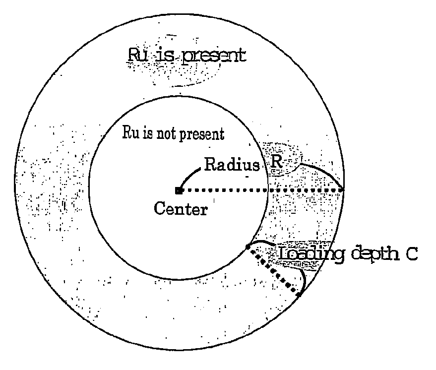
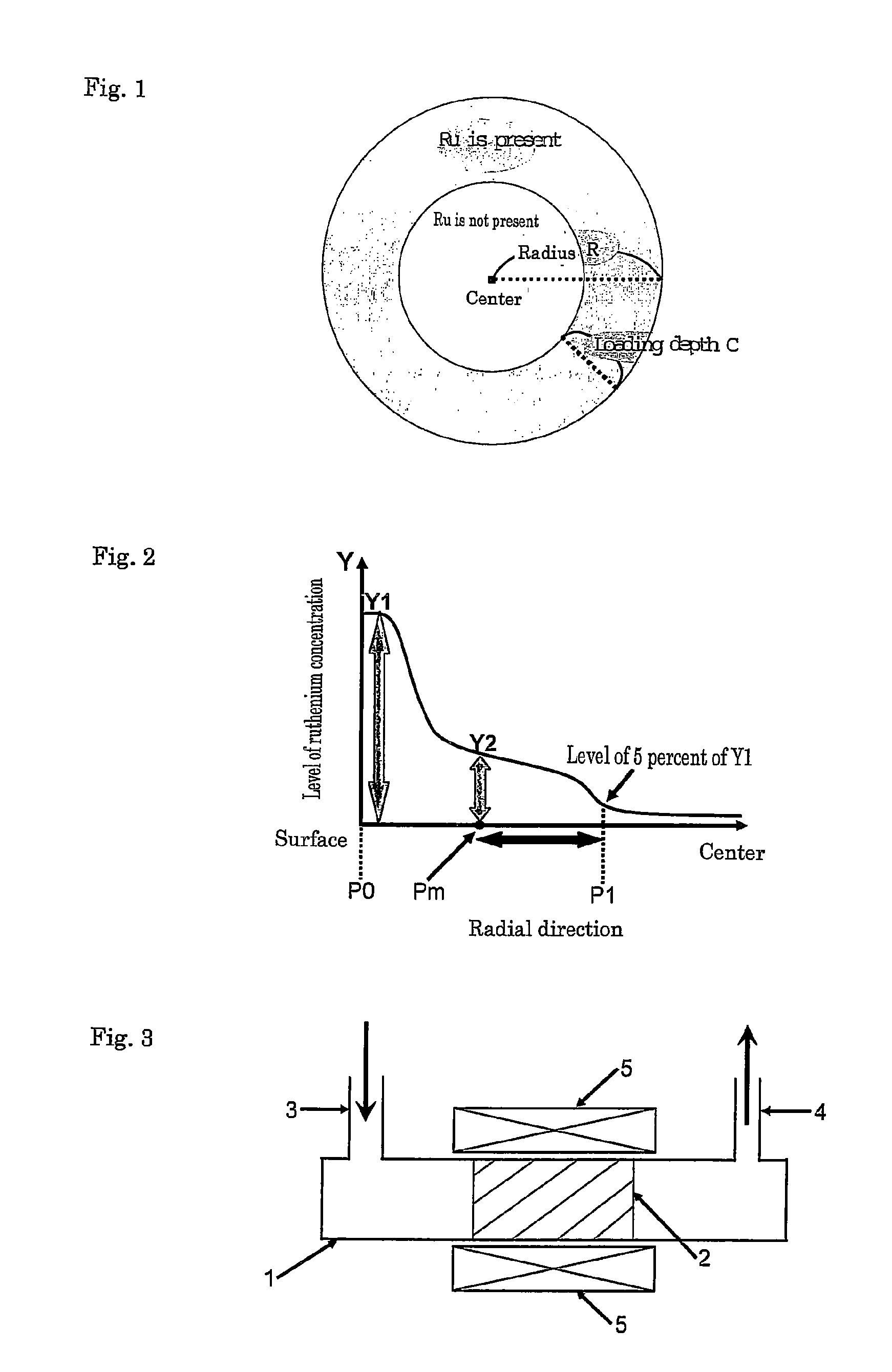
[0082]As shown in FIG. 5, for catalyst A1, the relative position where ruthenium was present was from 0 to 23 percent and thus the relative loading depth of ruthenium X(Ru)=23(%). That is, it was confirmed that catalyst A1 satisfied the requirement of formula (1) above. The resulting product gas had a CH4 concentration of 2,700 ppm by volume and a CO concentration of 3.2 ppm by volume. Therefore, catalyst A1 was able to reduce the CO concentration in the product gas to 5 ppm by volume or less because of its high methanation capability.

example 2

[0083]As shown in FIG. 6, for catalyst A2, the relative position where ruthenium was present was from 0 to 15 percent and thus the relative loading depth of ruthenium X(Ru)=15(%). That is, it was confirmed that catalyst A2 satisfied the requirement of formula (1) above. The resulting product gas had a CH4 concentration of 1,800 ppm by volume and a CO concentration of 3.4 ppm by volume. Therefore, catalyst A2 was able to reduce the CO concentration in the product gas to 5 ppm by volume or less because of its high methanation capability.

example 3

[0087]As shown in FIG. 5, for catalyst A1 of Example 1, Y1 / Y2=3.3 and thus it was confirmed that catalyst A1 satisfied the requirement defined by formula (3). The resulting product gas had a CH4 concentration of 2,700 ppm by volume and a CO concentration of 3.2 ppm by volume. Therefore, catalyst A1 was able to reduce the CO concentration in the product gas to 3.5 ppm by volume or less because of its high methanation capability. The results are also set forth in Table 1.


PUM

PropertyMeasurementUnit
pore diameteraaaaaaaaaa
temperatureaaaaaaaaaa
timeaaaaaaaaaa

Abstract

Disclosed in a catalyst which enables to reduce the carbon monoxide concentration in a product gas to 5 ppm by volume or less when carbon monoxide in a raw material gas containing hydrogen and carbon monoxide is selectively oxidized. The catalyst comprises a support of an inorganic oxide and ruthenium loaded thereon, and the relative loading depth X(Ru) of ruthenium in the radial direction in a redial cross-section of the catalyst satisfies the requirement defined by the following formula (1)X(Ru)≧15  (1).

Description

CROSS-REFERENCE TO RELATED APPLICATION[0001]This application is a section 371 of International Application No. PCT / JP2007 / 074614, filed Dec. 17, 2007, which was published in the Japanese language on Jun. 26, 2008 under International Publication No. WO 2008 / 075761 A1 and the disclosure of which is incorporated herein by reference.FIELD OF THE INVENTION[0002]The present invention relates to catalysts for oxidizing carbon monoxide selectively in a raw material gas containing carbon monoxide and hydrogen to produce a hydrogen-rich gas. More specifically, the present invention relates to such catalysts that can reduce the carbon monoxide concentration with their improved methanation capability.BACKGROUND OF THE INVENTION[0003]A fuel cell has characteristics that it is high in efficiency because it can take out electric energy directly from free energy changes caused by combustion of fuel. Further, the fuel cell does not discharge any harmful substance and thus have been extended to be us...

Claims


Application Information

Patent Timeline
Patent Type & Authority Patents(United States)
IPC IPC(8): B01J23/00C01F15/00C01F13/00C10K1/00C01G30/00C01G43/00C01G56/00C01G28/00C01B31/18C01B35/00C01B33/00C01B31/00C01B25/00C01B23/00C01B21/00B01D53/14B01D53/94B01D53/56B01D53/34B01D47/00B01J8/02B01J8/00B01J23/58B01J23/40B01J23/42C01B32/40
CPCB01J23/462B01J23/50B01J35/0073C01B3/583H01M8/0668B01J21/04B01J37/0201C01B2203/0233C01B2203/0244C01B2203/025C01B2203/0283C01B2203/0405C01B2203/042C01B2203/044C01B2203/0445C01B2203/047C01B2203/066Y02E60/50B01J35/396
Inventor IWASA, YASUYUKIMATSUMOTO, TAKAYA
Owner NIPPON OIL CORP
Learn More