Eureka AIR delivers breakthrough ideas for toughest innovation challenges, trusted by R&D personnel around the world.

Liquid crystal display device

a liquid crystal display and liquid crystal technology, applied in the direction of thin material processing, instruments, chemistry apparatus and processes, etc., can solve the problems of image sticking, unreacted portion of photopolymerizing compound remains in the liquid crystal layer, and reduce reliability

Active Publication Date: 2012-01-10
MERCK PATENT GMBH
View PDF15 Cites 25 Cited by
  • Summary
  • Abstract
  • Description
  • Claims
  • Application Information

AI Technical Summary

Benefits of technology

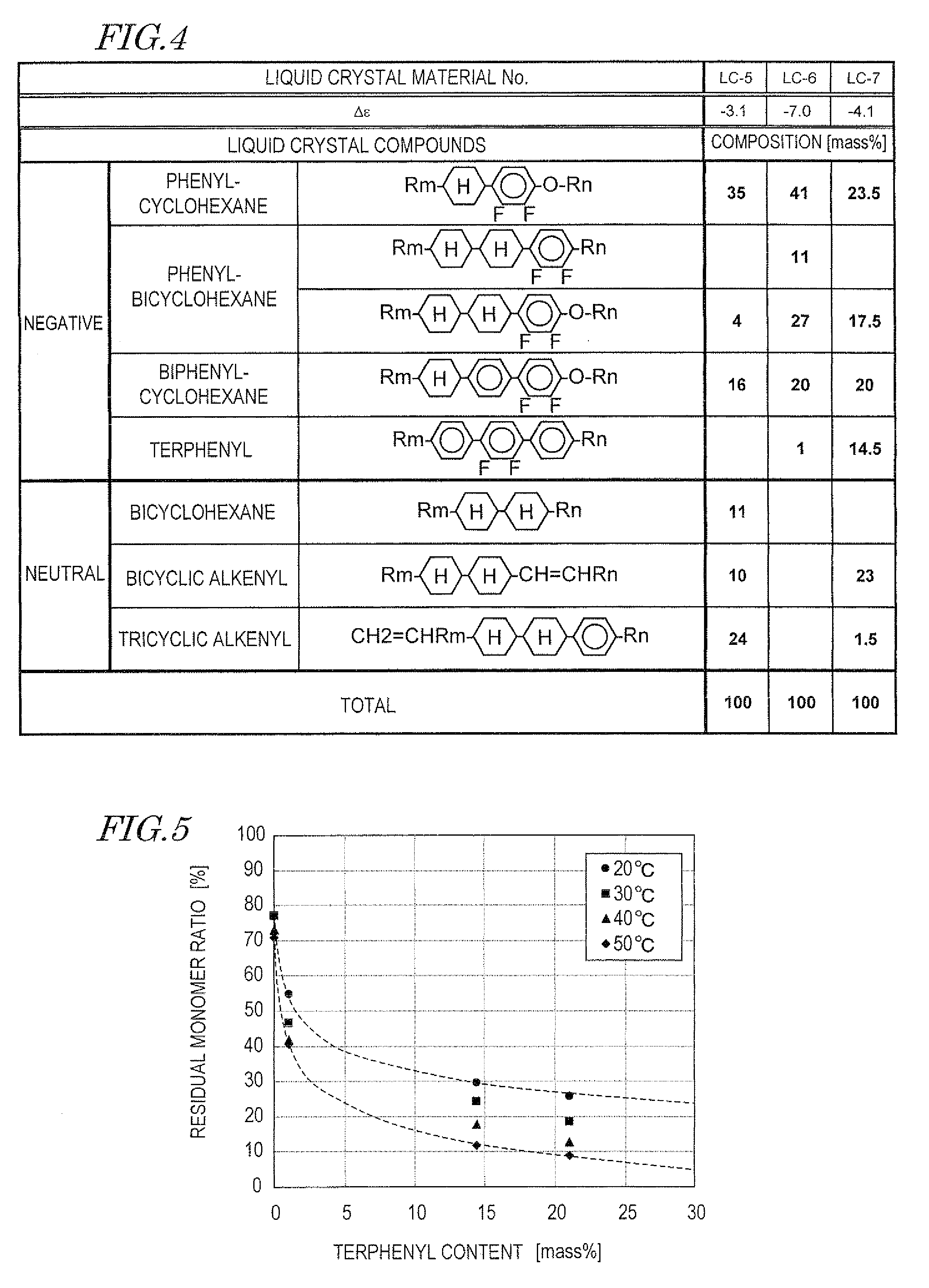
[0018]In a liquid crystal display device of the technology disclosed herein, a nematic liquid crystal material included in a liquid crystal layer contains a liquid crystal compound having a terphenyl ring system as an indispensable component. The liquid crystal compound having a terphenyl ring system has the function of increasing the efficiency of a polymerization reaction of a photopolymerizable compound in the liquid crystal layer. Therefore, in an end-product liquid crystal display device, the content of the photopolymerizable compound remaining in the liquid crystal layer relative to the nematic liquid crystal material can be less than 0.015 mol %. Further, the UV dose need not to be increased as compared with the conventional process. Thus, the liquid crystal display device of the technology disclosed herein is also advantageous in terms of reliability and production cost.

Problems solved by technology

However, in the PSA technology, an insufficient UV dose leads to a problem that an unreacted portion of a photopolymerizable compound remains in the liquid crystal layer.
If this phenomenon occurs, it may emerge in the form of image sticking.
The ultraviolet light can damage the liquid crystal material and the organic materials of the alignment films and other constituents and can therefore decrease the reliability.
Thus, the UV dose cannot be inordinately increased.
This leads to an increase in production cost.

Method used


Image

  • Liquid crystal display device
  • Liquid crystal display device
  • Liquid crystal display device

Examples


Embodiment Construction

[0027]Hereinafter, a liquid crystal display device of an embodiment of the technology disclosed herein is described with reference to the drawings. The technology disclosed herein is not limited to the embodiment described below.

[0028][Liquid Crystal Display Device Fabricated Using PSA Technology]

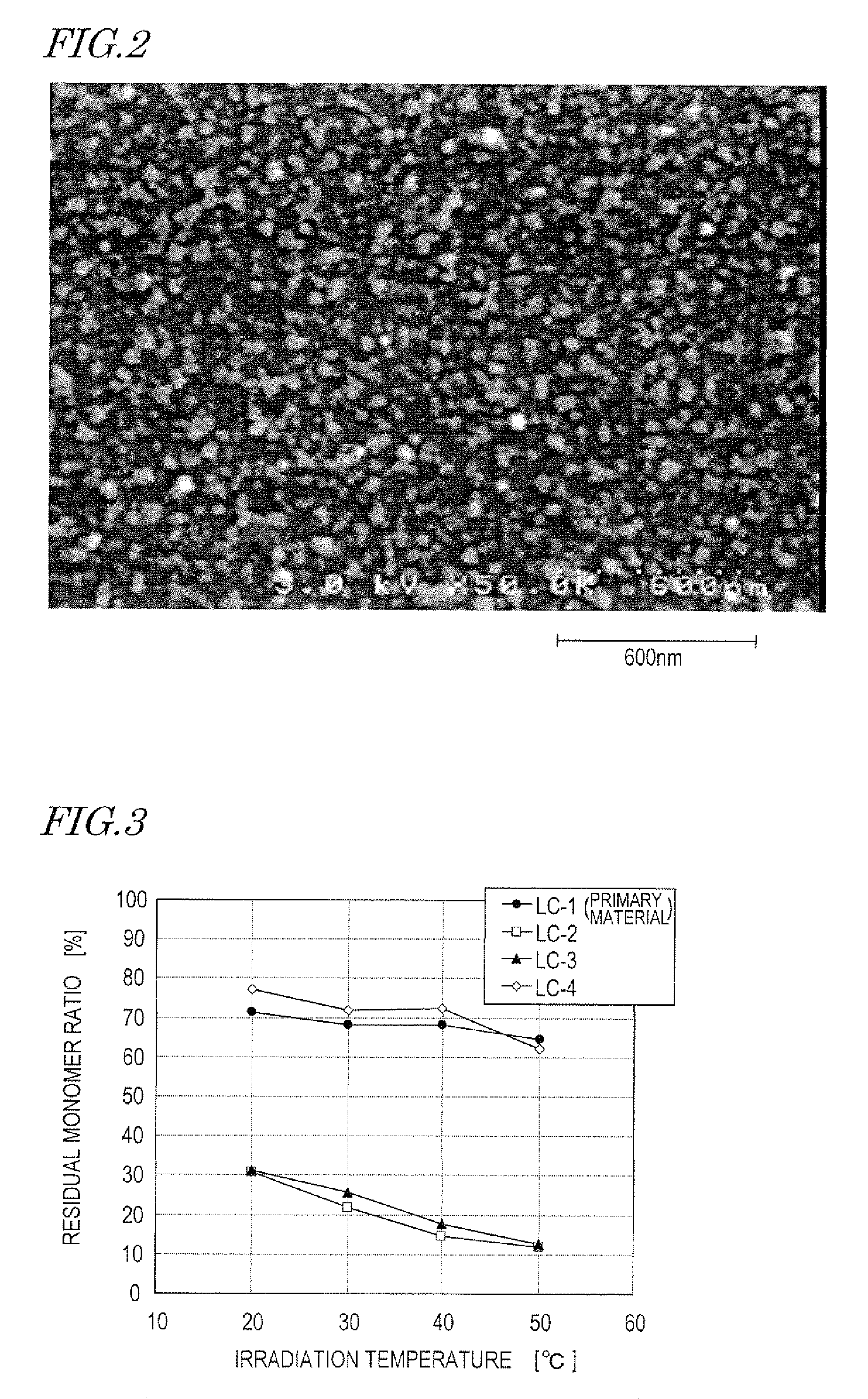
[0029]First, a structure and operation of a liquid crystal display device fabricated using the PSA technology are described with reference to FIG. 1 and FIG. 2.

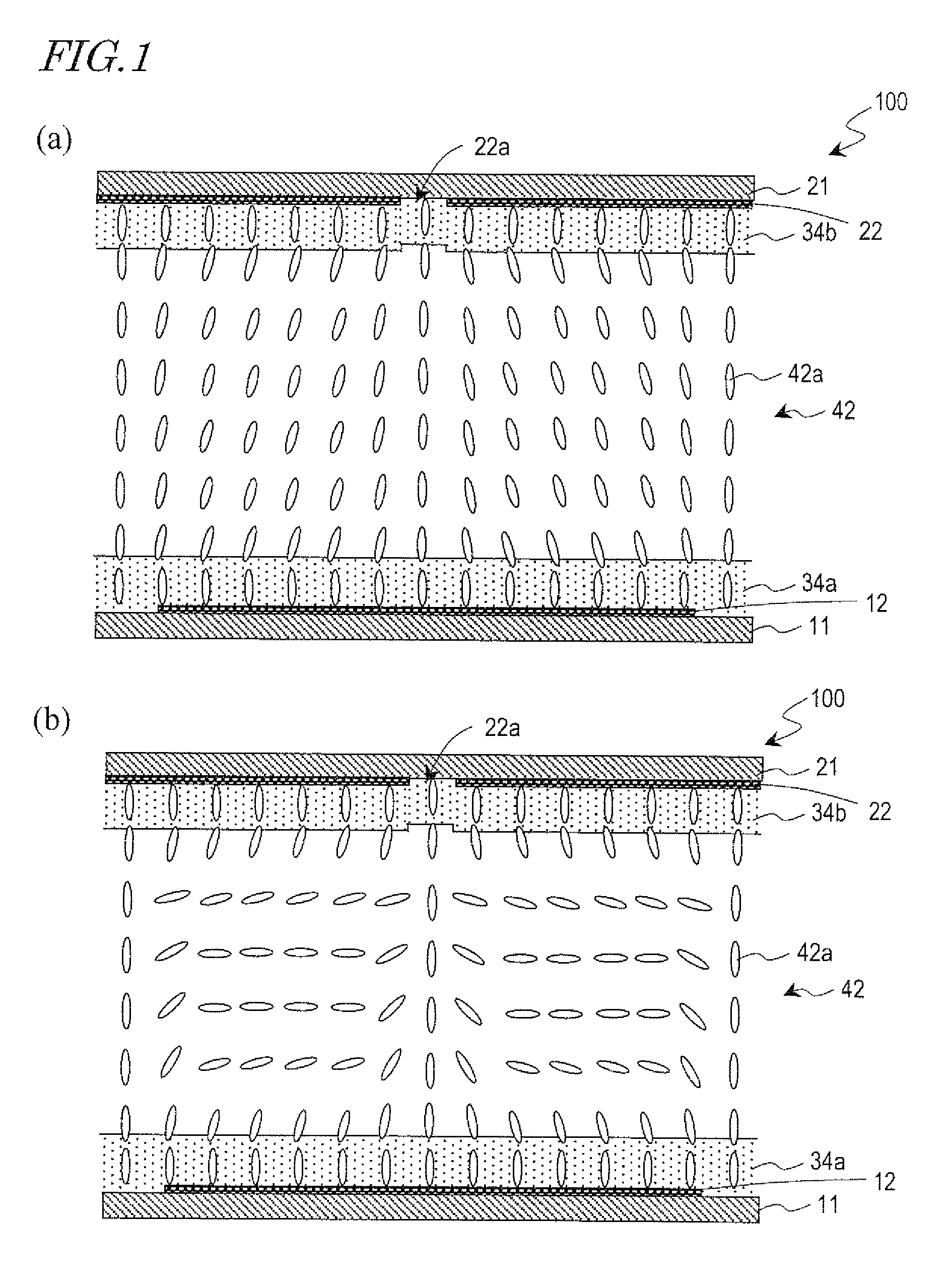
[0030]FIG. 1 is a cross-sectional view schematically showing a structure of one pixel of a liquid crystal display device 100 of an embodiment of the technology disclosed herein. FIG. 1(a) shows an alignment of liquid crystal molecules 42a in a black display state (in the absence of an applied voltage). FIG. 1(b) shows an alignment of the liquid crystal molecules 42a in a white display state (in the presence of an applied voltage). Hereinafter, the embodiment of the technology disclosed herein is described with an example of a vertica...


PUM

PropertyMeasurementUnit
particle diameteraaaaaaaaaa
pretilt angleaaaaaaaaaa
mass %aaaaaaaaaa

Abstract

A liquid crystal display device of the present invention includes: a liquid crystal layer containing a nematic liquid crystal material; a pair of electrodes opposing each other via the liquid crystal layer; a pair of alignment films respectively provided between the pair of electrodes and the liquid crystal layer; and an alignment sustaining layer formed of a photopolymerized material on each of surfaces of the pair of alignment films which are closer to the liquid crystal layer, the alignment sustaining layer being configured to regulate a pretilt azimuth of a liquid crystal molecule of the liquid crystal layer during the absence of an applied voltage across the liquid crystal layer, wherein the pretilt azimuth of the liquid crystal molecule of the liquid crystal layer is regulated by the alignment sustaining layer during the absence of an applied voltage across the liquid crystal layer. The nematic liquid crystal material contains a liquid crystal compound having a terphenyl ring system as an indispensable component, and the liquid crystal layer further contains part of a photopolymerizable compound which is a source material of the photopolymerized material, a content of the photopolymerizable compound relative to the nematic liquid crystal material being less than 0.015 mol %.

Description

[0001]This application is the U.S. national phase of International Application No. PCT / JP2008 / 002873, filed 10 Oct. 2008, which designated the U.S. and claims priority to Japanese Patent Application No. 2007-267479, filed 15 Oct. 2007, the entire contents of each of which are hereby incorporated by reference.TECHNICAL FIELD[0002]The present invention relates to a liquid crystal display device and specifically to a liquid crystal display device which uses the Polymer Sustained Alignment Technology.BACKGROUND ART[0003]Liquid crystal display devices perform display by utilizing the change of the orientations of liquid crystal molecules which is caused by a voltage applied across the liquid crystal layer. The orientations of the liquid crystal molecules which occur in the absence of an applied voltage across the liquid crystal layer (pretilt directions) are conventionally regulated by alignment films. For example, in TN-mode liquid crystal display devices, the pretilt azimuths of the li...

Claims


Application Information

Patent Timeline
Patent Type & Authority Patents(United States)
IPC IPC(8): C09K19/00C09K19/32C09K19/52C09K19/06
CPCG02F1/133711G02F1/133788Y10T428/10Y10T428/1005Y10T428/1036C09K2323/00C09K2323/02C09K2323/03
Inventor USUI, KENTAROTANUMA, SEIJIHANAOKA, KAZUTAKANAKAMURA, KIMIAKI
Owner MERCK PATENT GMBH
Why Eureka
Eureka Blog
Learn More