
Electronic system and heat dissipation device thereof

a technology of electronic system and heat dissipation device, which is applied in the direction of power cables, semiconductor/solid-state device details, cables, etc., can solve the problems of insufficient space in the electronic system to respectively meet lone conventional heat sinks cannot make the required snug contact with the top surfaces of all components, and damage to the electronic components

Inactive Publication Date: 2011-12-27
FU ZHUN PRECISION IND SHENZHEN +1
View PDF3 Cites 7 Cited by
  • Summary
  • Abstract
  • Description
  • Claims
  • Application Information

AI Technical Summary

Benefits of technology

The solution enables efficient heat transfer and simplified assembly by eliminating the need for screws and tools, ensuring stable mounting of heat pipes and reducing the risk of deformation during transport and assembly, thereby improving overall heat dissipation performance.

Problems solved by technology

If the heat is not efficiently removed, the electronic components may suffer damage.
Since the electronic components are generally of different heights with top surfaces thereof at different levels, a lone conventional heat sink cannot make the required snug contact with the top surfaces of all the components.
However, there may not be sufficient space in the electronic system to respectively secure the heat pipes on the electronic components via plural sets of screws.
This complicates the assembly of the heat dissipation device.

Method used


Image

  • Electronic system and heat dissipation device thereof
  • Electronic system and heat dissipation device thereof
  • Electronic system and heat dissipation device thereof

Examples


Embodiment Construction

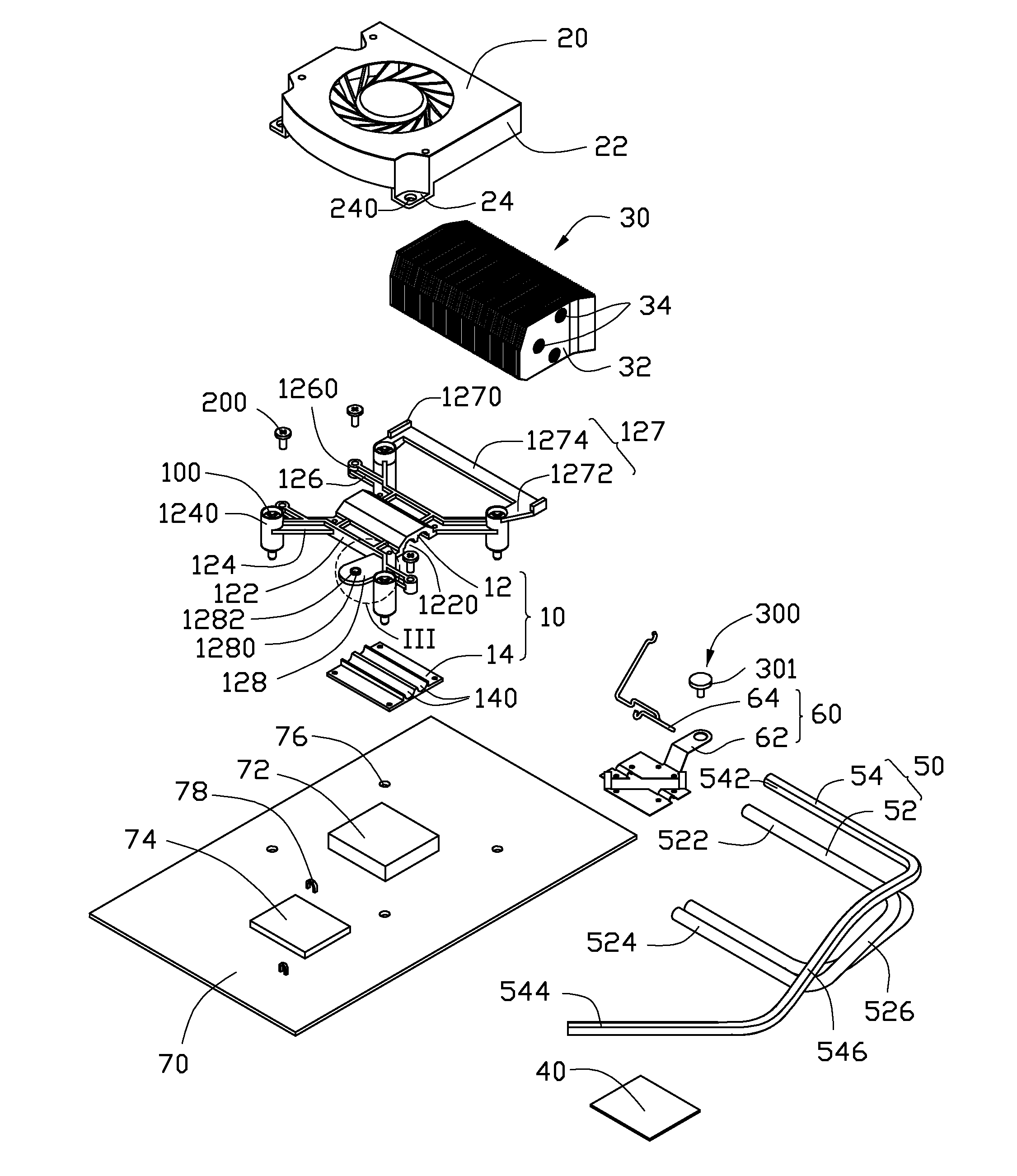
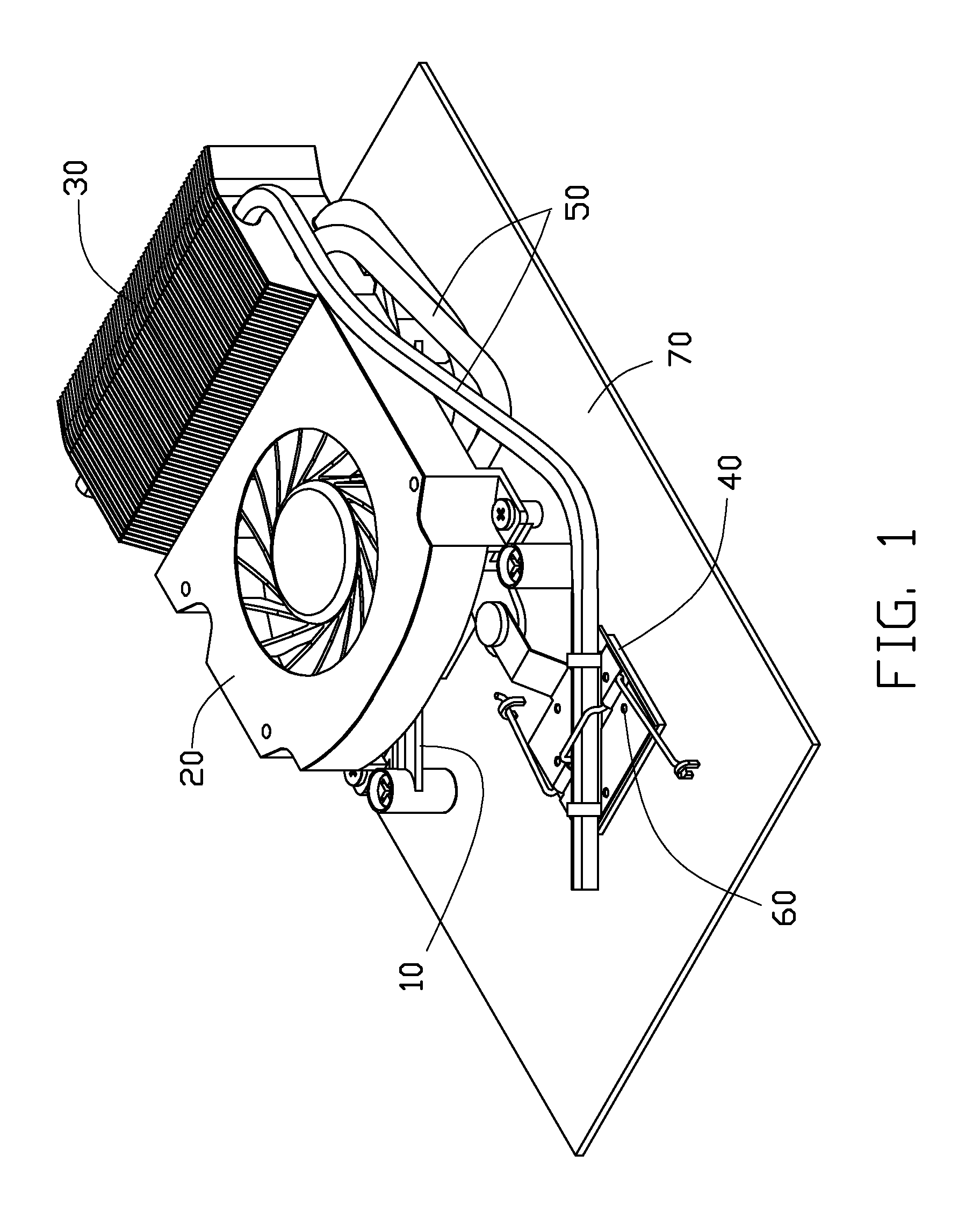
Referring to FIGS. 1 and 2, an electronic system in accordance with one embodiment of the disclosure is shown. The electronic system includes a circuit board 70, and a heat dissipation device mounted on the circuit board 70. The circuit board 70 supports a first electronic component 72 such as a CPU, and a second electronic component 74 such as an MCH, ICH, or other component. In the illustrative embodiment, the first electronic component 72 generates more heat than the second electronic component 74 during operation. The circuit board 70 defines therein a mounting hole 76 near each corner of the first electronic component 72, and provides a pair of clasps 78 near two diagonally opposite corners of the second electronic component 74. The heat dissipation device includes a first base 10 mounted on the first electronic component 72, a fan 20 located on the first base 10, a fin assembly 30 disposed beside the fan 20, a second base mounted on the second electronic component 74, and a he...


PUM


Abstract

A heat dissipation device for an electronic component mounted on a circuit board includes a heat pipe and a fastening assembly. The heat pipe includes an evaporation section and a condensation section. The fastening assembly includes a retention plate and a wire clip. The retention plate includes a retaining portion abutting against the heat pipe, and two fastening portions located at opposite sides of the evaporation section of the heat pipe. The wire clip includes two abutting portions, a resisting portion interconnecting the abutting portions, and two locking arms extending outwardly from two outer ends of the abutting portions, respectively. The retaining portion and the resisting portion abut against the evaporation section of the heat pipe, the abutting portions abut against inner surfaces of the fastening portions, the locking arms are fastened to the circuit board, thereby mounting the retention plate with the heat pipe on the electronic component.

Description

CROSS-REFERENCE TO RELATED APPLICATIONThis application is related to a co-pending application entitled “HEAT DISSIPATION DEVICE AND ELECTRONIC SYSTEM INCORPORATING THE SAME”, assigned to the same assignee of this application and filed on the same date as this application.BACKGROUND1. Technical FieldThe disclosure generally relates to heat dissipation, and particularly to a heat dissipation device with a wire clip and an electronic system incorporating the heat dissipation device.2. Description of Related ArtIt is well known that heat is generated by electronic components, such as integrated circuit chips, during their operation. If the heat is not efficiently removed, the electronic components may suffer damage. Thus, heat dissipation devices are often used to cool the electronic components.In a typical computer system, more than one electronic component, such as a central processing unit (CPU), a memory control hub (MCH), an input / output (i / o) controller hub (ICH), and others, must...

Claims


Application Information

Patent Timeline
Patent Type & Authority Patents(United States)
IPC IPC(8): H05K7/20
CPCG06F1/20H01L23/4093H01L23/427H01L23/467H01L2924/0002H01L2924/00
Inventor YANG, JIAN
Owner FU ZHUN PRECISION IND SHENZHEN
Learn More