
Method of operating semiconductor memory device with floating body transistor using silicon controlled rectifier principle

a technology of floating body transistor and rectifier principle, which is applied in the direction of semiconductor devices, digital storage, instruments, etc., can solve the problems of inefficient consumption and energy consumption, and difficulty in generating

Active Publication Date: 2011-12-13
ZENO SEMICON
View PDF78 Cites 178 Cited by
  • Summary
  • Abstract
  • Description
  • Claims
  • Application Information

AI Technical Summary

Benefits of technology

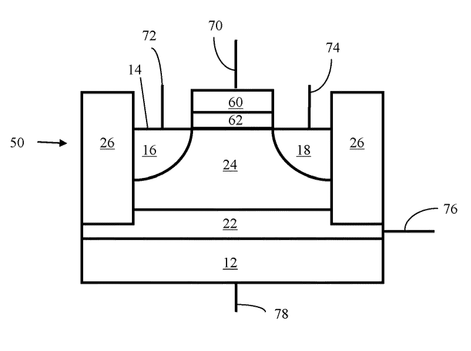
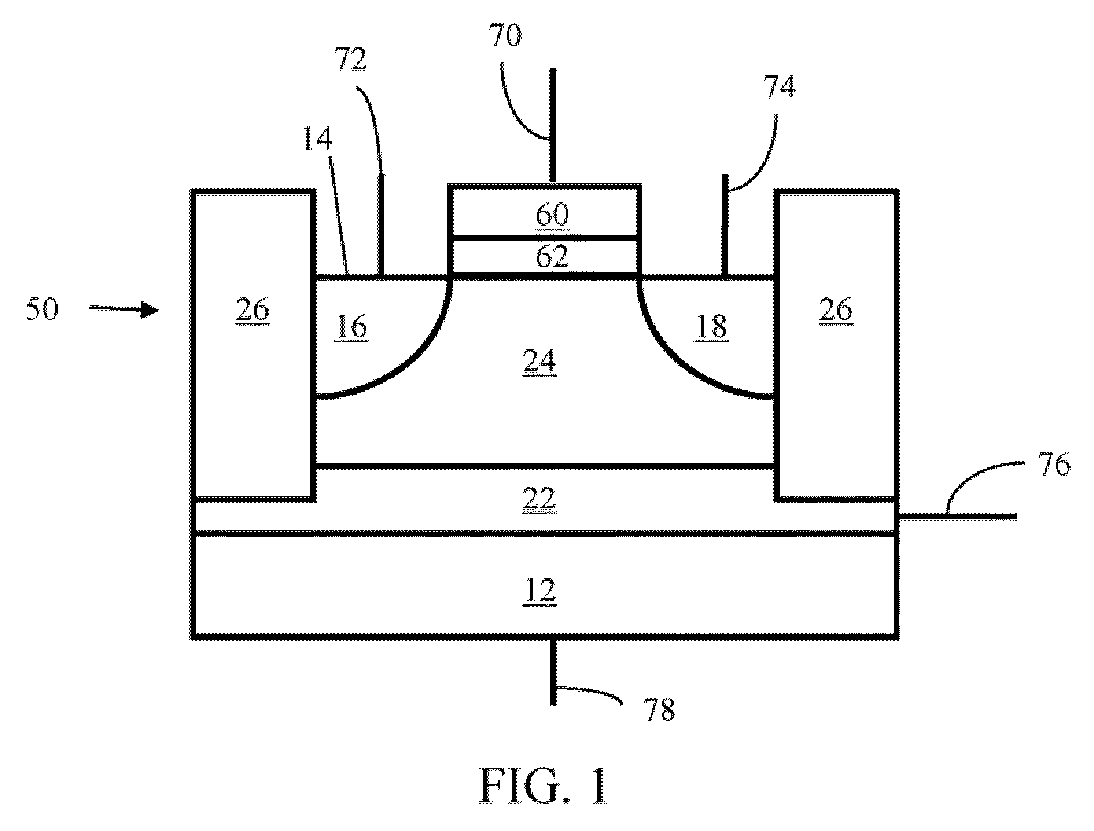
The present invention provides methods for operating semiconductor memory devices with floating body transistors using a silicon controlled rectifier principle. The methods involve maintaining the data state of a memory cell by applying a positive voltage to a substrate terminal and a source line terminal, while a negative voltage is applied to a word line terminal and a buried well terminal. The memory cell includes a substrate, a first region, a second region, a buried layer, a body region, and a gate. The methods also involve applying a substantially neutral voltage to the bit line terminal and the source line terminal, and allowing the voltage levels of the source line terminal and the buried well terminal to float. The invention provides a semiconductor memory array with the memory cells arranged in a matrix of rows and columns.

Problems solved by technology

As the 1T / 1C memory cell feature is being scaled, difficulties arise due to the necessity of maintaining the capacitance values of each memory scale in the scaled architecture.
This process must be repeated cyclically after each passage of a predetermined period of time, and is inefficient, as it is both time consuming and energy inefficient.

Method used


Image

  • Method of operating semiconductor memory device with floating body transistor using silicon controlled rectifier principle
  • Method of operating semiconductor memory device with floating body transistor using silicon controlled rectifier principle
  • Method of operating semiconductor memory device with floating body transistor using silicon controlled rectifier principle

Examples


Embodiment Construction

[0040]Before the present devices and methods are described, it is to be understood that this invention is not limited to particular embodiments described, as such may, of course, vary. It is also to be understood that the terminology used herein is for the purpose of describing particular embodiments only, and is not intended to be limiting, since the scope of the present invention will be limited only by the appended claims.

[0041]Where a range of values is provided, it is understood that each intervening value, to the tenth of the unit of the lower limit unless the context clearly dictates otherwise, between the upper and lower limits of that range is also specifically disclosed. Each smaller range between any stated value or intervening value in a stated range and any other stated or intervening value in that stated range is encompassed within the invention. The upper and lower limits of these smaller ranges may independently be included or excluded in the range, and each range wh...


PUM


Abstract

A method of maintaining the data state of a semiconductor dynamic random access memory cell is provided, wherein the memory cell comprises a substrate being made of a material having a first conductivity type selected from p-type conductivity type and n-type conductivity type; a first region having a second conductivity type selected from the p-type and n-type conductivity types, the second conductivity type being different from the first conductivity type; a second region having the second conductivity type, the second region being spaced apart from the first region; a buried layer in the substrate below the first and second regions, spaced apart from the first and second regions and having the second conductivity type; a body region formed between the first and second regions and the buried layer, the body region having the first conductivity type; and a gate positioned between the first and second regions and adjacent the body region.

Description

[0001]This application claims the benefit of U.S. Provisional Application No. 61 / 086,170 filed Aug. 5, 2008, which application is hereby incorporated herein, in its entirety, by reference thereto.FIELD OF THE INVENTION[0002]The present invention relates to semiconductor memory technology. More specifically, the present invention relates to dynamic random access memory having an electrically floating body transistor.BACKGROUND OF THE INVENTION[0003]Semiconductor memory devices are used extensively to store data. Dynamic Random Access Memory (DRAM) is widely used in many applications. Conventional DRAM cells consist of a one-transistor and one-capacitor (1T / 1C) structure. As the 1T / 1C memory cell feature is being scaled, difficulties arise due to the necessity of maintaining the capacitance values of each memory scale in the scaled architecture.[0004]There is a need in the art for improve DRAM memory that can better retain capacitance values in the cells of a scaled architecture compr...

Claims


Application Information

Patent Timeline
Patent Type & Authority Patents(United States)
IPC IPC(8): G11C7/00H10B12/00
CPCG11C11/404G11C11/4076H01L27/10802H01L29/7841G11C2211/4016H10B12/20G11C11/406G11C11/4096
Inventor WIDJAJA, YUNIARTO
Owner ZENO SEMICON
Learn More