
System and method for analyzing faulty event transmissions

a technology of event transmission and event detection, applied in the field of security system event transmission fault detection, can solve the problems of difficult to ascertain, failure to automatically record faulty event transmission signals, and failure to detect and diagnose fault conditions, and achieve the effect of increasing the efficiency of detecting and diagnosing fault conditions

Active Publication Date: 2011-12-13
JOHNSON CONTROLS TYCO IP HLDG LLP
View PDF7 Cites 0 Cited by
  • Summary
  • Abstract
  • Description
  • Claims
  • Application Information

AI Technical Summary

Benefits of technology

[0008]The disclosed system increases the efficiency of detecting and diagnosing fault conditions associated with communications between alarm system sites and central monitoring facilities. In addition to detecting problems with panels and communications links, the system can also detect whether conditions within the central monitoring facility's receiver are causing or contributing to the fault. Recorded fault data is fully indexed in memory associated with the receiver or a connected device, thus enabling quick location of the data for review.

Problems solved by technology

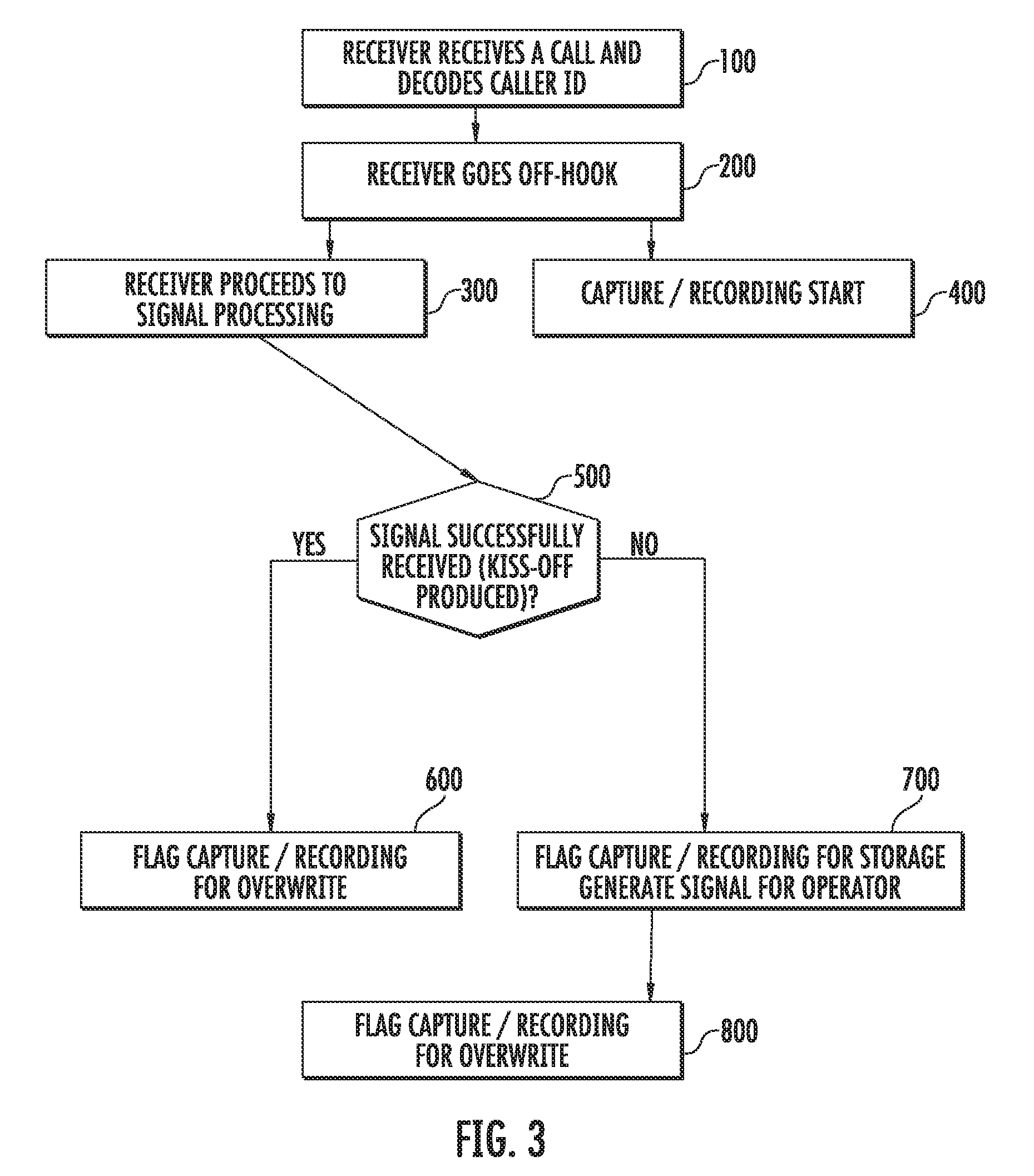
During regular event transmissions from a DACT to the central monitoring facility there are sometimes instances in which the transmission is not successful, either because the quality of the transmission is substandard or because the information is not transmitted in a format that is acceptable to the receiver.
These instances can range in root cause and can prove difficult to ascertain as to whether they constitute “one off” problems or whether they constitute failures requiring systematic troubleshooting.
Current systems, however, do not automatically record faulty event transmission signals.
Rather, they typically only notify an operator that a faulty transmission has occurred on a particular line, but by that time the event has passed.
The current manual review process is often plagued by problems such as poor recording, lack of precisely calibrated equipment, unknown time frame of the fault recording, and the like.
In addition, the add-on recording equipment may record large volumes of signal data while waiting for the “next” fault to occur on the line.
Further, since the add-on recording equipment may not be time-stamped in perfect sync with the system receiver, it can be time consuming for the reviewer to locate the recorded faulty signal data.
This slows the review process and, thus, slows final resolution of the problem.
Moreover, adding recording equipment to the phone line in parallel or series with the receiver can affect the signal, thus hindering effective analysis of the signal once it is recorded.
In addition, since the added equipment typically records the signal upstream of the receiver, such an arrangement can fail to detect signal problems caused by the receiver.
Thus, if the ultimate problem resides in the manner in which the receiver is processing the signal, such a problem will not be detected with current systems.

Method used


Image

  • System and method for analyzing faulty event transmissions
  • System and method for analyzing faulty event transmissions
  • System and method for analyzing faulty event transmissions

Examples


Embodiment Construction

[0014]The present invention will now be described more fully hereinafter with reference to the accompanying drawings, in which preferred embodiments of the invention are shown. It will be appreciated, however, that the invention may be embodied in many different forms and should not be construed as limited to the embodiments set forth herein. Rather, these embodiments are provided so that this disclosure will be thorough and complete, and will fully convey the scope of the invention to those skilled in the art. In the drawings, like numbers refer to like elements throughout.

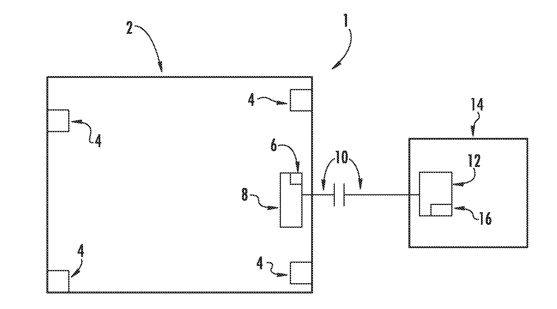
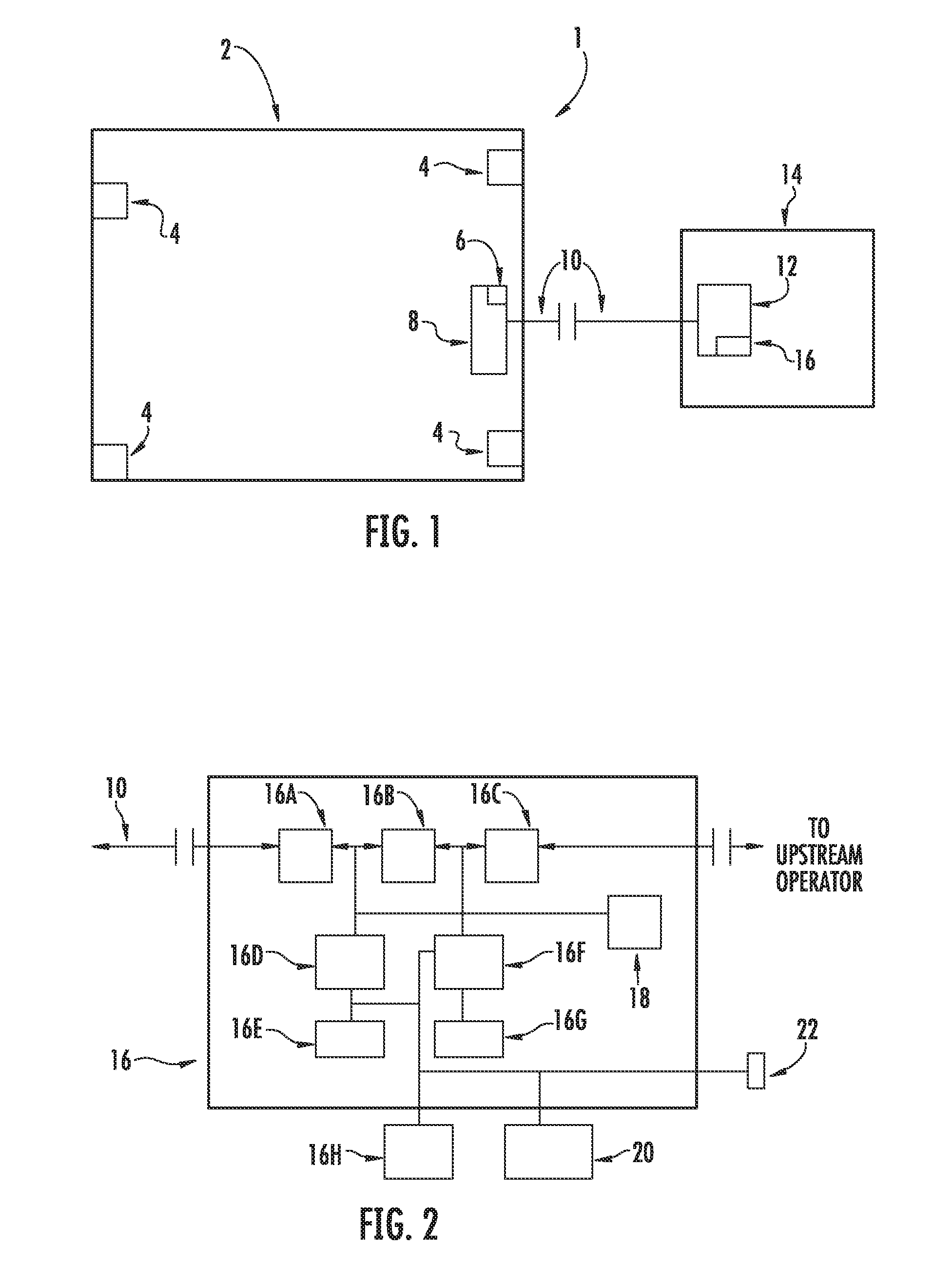
[0015]Referring to FIG. 1, a system 1 is shown for providing remote monitoring of a commercial or residential building 2. The system 1 may include a plurality of sensors 4 positioned throughout the building, and a Digital Alarm Communicator Transmitter (DACT) 6 housed within a security system panel 8. The DACT 6 may be in communication with the plurality of sensors 4 to receive signals therefrom. The connections ...


PUM


Abstract

A system and method are disclosed for recording and evaluating faults in event transmissions between security system components. A panel in a monitored building may send event signals to a receiver located in a central monitoring facility. Event signals may represent a status of individual alarms or sensors in the building, or they may provide a status of the system as a whole. If the quality of the transmission is substandard or in a format that is unacceptable to the receiver, the signal data associated with the event is recorded for analysis. Recording is controlled by a line card associated with the receiver, and the signal data is stored in local or remote memory. Signal data can be manually or automatically analyzed to determine the source of the fault. In addition, recorded signal data can be used to build customized software to recognize signals from previously unrecognized or faulty panels.

Description

FIELD OF THE INVENTION[0001]Embodiments of the invention relate to the field of fault detection for security system event transmissions. More particularly, embodiments of the invention relate to a system and method for recording and evaluating faults in event transmissions between security system components.DISCUSSION OF RELATED ART[0002]Typical building alarm systems often include a number of notification appliances positioned throughout a building to alert occupants of fire and non-fire emergencies. These notification appliances may include smoke detectors, fire alarms, security alarms, emergency lighting, strobe lighting, and the like. In addition to these notification appliances, building alarm systems may include components, such as a Digital Alarm Communicator Transmitter (DACT), that provide a communications link between the building in which the alarm system is located and a receiver in a central monitoring facility that is geographically remote from the building. The commun...

Claims


Application Information

Patent Timeline
Patent Type & Authority Patents(United States)
IPC IPC(8): G08B19/00
CPCH04Q9/00H04Q2209/10H04Q2209/86H04Q2209/823
Inventor FOISY, STEPHANE
Owner JOHNSON CONTROLS TYCO IP HLDG LLP
Learn More