
Light source device and projector having same

a technology of light source device and projector, which is applied in the field of projection technology, can solve the problem of limited brightness of projected imag

Inactive Publication Date: 2011-11-29
HON HAI PRECISION IND CO LTD
View PDF4 Cites 3 Cited by
  • Summary
  • Abstract
  • Description
  • Claims
  • Application Information

AI Technical Summary

Benefits of technology

The patent text describes a light source device and a projector that use a single light source device and a color wheel to produce high-brightness visual images. The technical effect of the patent is to overcome limitations in brightness caused by using a single light source device and to provide a more powerful and efficient light source for projectors. The patent describes different embodiments of the light source device and the projector, including different reflective assemblies and a convex lens. The reflective assembly includes a first mirror and a second mirror that reflect the light beams generated by the light source device back to the first reflector. The first mirror and the second mirror are positioned perpendicular to the optical axis and the reflective assembly is designed to defocus the light beams reflected by the second mirror as parallel light beams to the condensing lens. The integrated rod and the DMD work together to produce high-brightness visual images.

Problems solved by technology

However, when a projector is constructed using a single light source device, the brightness of the projected image is limited.

Method used


Image

  • Light source device and projector having same
  • Light source device and projector having same
  • Light source device and projector having same

Examples


Embodiment Construction

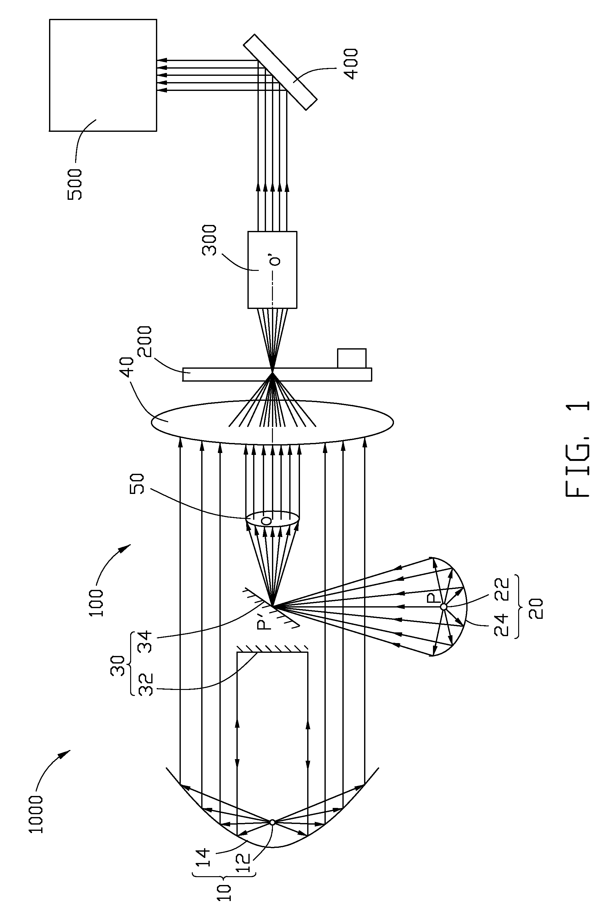
[0010]Referring to FIG. 1, a projector 1000, according to a first exemplary embodiment, includes a light source device 100, a color wheel 200, an integration rod 300, a digital micro-mirror device 400 (DMD), and a projection lens 500 along light path of light emitted from the light source device 100 in that order.

[0011]The light source device 100 includes a first light source 10, a second light source 20, a reflective assembly 30, a condensing lens 40 defining an optical axis OO′, and a convex lens 50. The first light source 10, the reflective assembly 30, the convex lens 50, and the condensing lens 40 are arranged in order along the optical axis OO′. The second light source 20 corresponds to the reflective assembly 30 and is deviated from the optical axis OO′.

[0012]The first light source 10 includes a first lamp 12 and a first reflector 14. The first lamp 12, such as a high pressure mercury lamp, a metal halide lamp, or a xenon lamp, is configured for generating white light beams. ...


PUM


Abstract

A light source device includes a first light source, a second light source, a reflective assembly, and a condensing lens defining an optical axis. The first light source includes a first lamp and a first reflector reflecting light beams generated by the first lamp as first parallel light beams. The second light source includes a second lamp and a second reflector reflecting light beams generated by the second lamp. The first light source, the reflective assembly and the condensing lens are arranged in order along the optical axis. The second light source corresponds to the reflective assembly deviated from the optical axis. The reflective assembly reflects light beams reflected by the first reflector back to the first reflector, and reflects light beams from the second reflector to the condensing lens. The condensing lens condenses the first parallel light beams and the light beams reflected by the reflective assembly.

Description

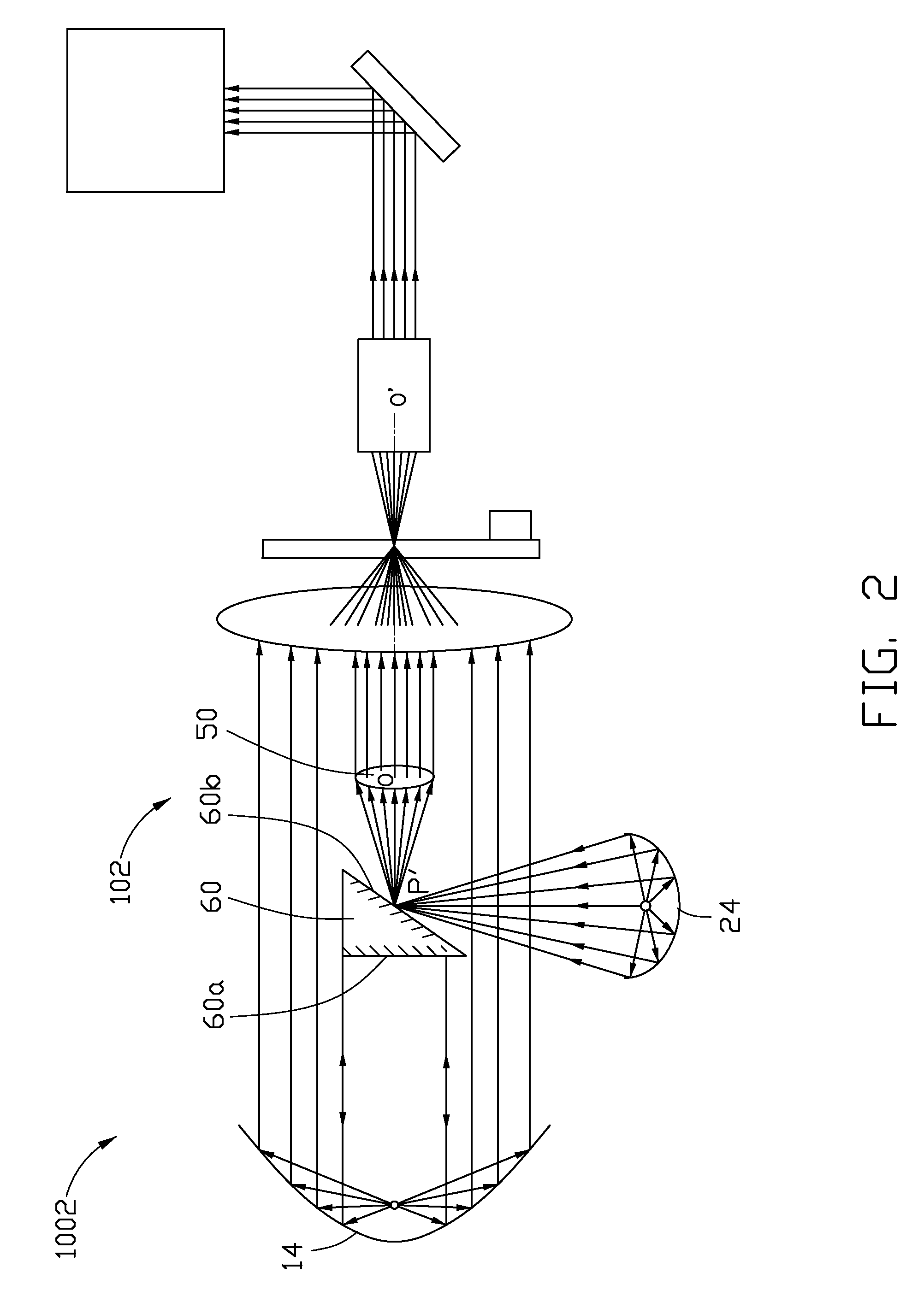
BACKGROUND[0001]1. Technical Field[0002]The disclosure relates to projection technology and, particularly, to a light source device and a projector having the same.[0003]2. Description of the Related Art[0004]Light source devices, such as high pressure mercury lamps, metal halide lamps, or xenon lamps, used in projectors are configured for generating white light beams and, in cooperation with a digital micro-mirror device (DMD) and a color wheel, to project a color image. To obtain a projected image with high brightness, it is required to increase the power of the light source devices. However, when a projector is constructed using a single light source device, the brightness of the projected image is limited.[0005]Therefore, what is needed is a light source device and a projector using the same which can overcome the described limitations.BRIEF DESCRIPTION OF THE DRAWINGS[0006]FIG. 1 is a schematic view of a projector, according to a first exemplary embodiment.[0007]FIG. 2 is a sch...

Claims


Application Information

Patent Timeline
Patent Type & Authority Patents(United States)
IPC IPC(8): G03B21/26F21V7/00F21V13/00G03B21/14H04N5/74G03B21/28G02B5/10
CPCG03B21/28
Inventor YEH, HSIN-TSUNGHUANG, CHUN-HSIANGCHANG, WEI-HSIULIN, KUANG-WEICHEN, KUAN-TINGLIN, MEI-CHUN
Owner HON HAI PRECISION IND CO LTD
Learn More