
Coarse frequency offset estimation in ISDB receivers

a frequency offset and receiver technology, applied in the field of coarse frequency offset estimation in wireless communication systems, can solve the problems of coarse frequency offset, frequency offset usually arises, and the approach of coarse frequency offset estimation based on the raised power property of pilots, tmcc, etc., and achieves high doppler and noisy channels.

Inactive Publication Date: 2011-11-22
ATMEL CORP
View PDF4 Cites 11 Cited by
  • Summary
  • Abstract
  • Description
  • Claims
  • Application Information

AI Technical Summary

Benefits of technology

The patent text describes a method for estimating a coarse frequency offset in a receiver. The method involves modulating the TMCC bins and AC bins in OFDM symbols with DBPSK modulation, estimating the phase difference between a first symbol and a second symbol, correcting the phase difference based on a difference between the candidate frequency offset and a FFT center bin, mapping the corrected phase difference to numeric numbers, and adding the numeric numbers for the candidate frequency offset and the AC bins to obtain a summation result. The technical effect of this method is to provide a reliable and accurate way to estimate the coarse frequency offset in a receiver, which can be used to improve the performance and reliability of the receiver in various transmission modes.

Problems solved by technology

In a digital broadcasting receiver design such as Integrated Services Digital Broadcasting-terrestrial (ISDB-T) and Integrated Services Digital Broadcasting—terrestrial digital sound broadcasting (ISDB-TSB), the major disadvantage for OFDM systems is its impairment due to coarse frequency offset.
Frequency offsets usually arise due to mismatched transmitter and receiver oscillators.
An approach for coarse frequency offset estimation based on the raised power property of pilot, TMCC, and AC bins is generally not reliable, especially when the channels are noisy and dynamic and there are echoes.

Method used


Image

  • Coarse frequency offset estimation in ISDB receivers
  • Coarse frequency offset estimation in ISDB receivers
  • Coarse frequency offset estimation in ISDB receivers

Examples


Embodiment Construction

The embodiments herein and the various features and advantageous details thereof are explained more fully with reference to the non-limiting embodiments that are illustrated in the accompanying drawings and detailed in the following description. Descriptions of well-known components and processing techniques are omitted so as to not unnecessarily obscure the embodiments herein. The examples used herein are intended merely to facilitate an understanding of ways in which the embodiments herein may be practiced and to further enable those of skill in the art to practice the embodiments herein. Accordingly, the examples should not be construed as limiting the scope of the embodiments herein.

Referring now to the drawings, and more particularly to FIGS. 1 through 6, where similar reference characters denote corresponding features consistently throughout the figures, there are shown preferred embodiments. The embodiments herein provide approaches for coarse frequency offset estimation in I...


PUM


Abstract

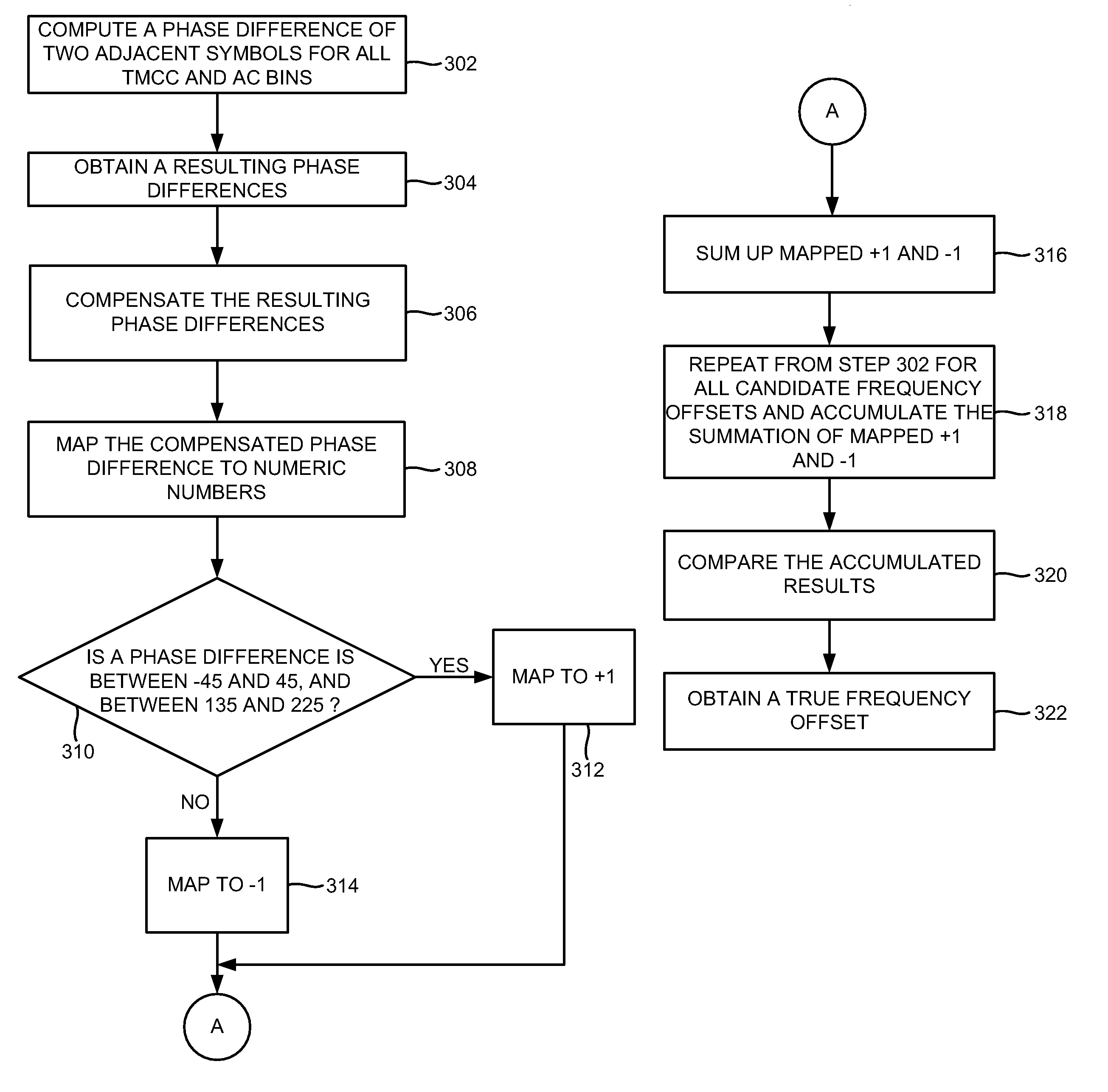
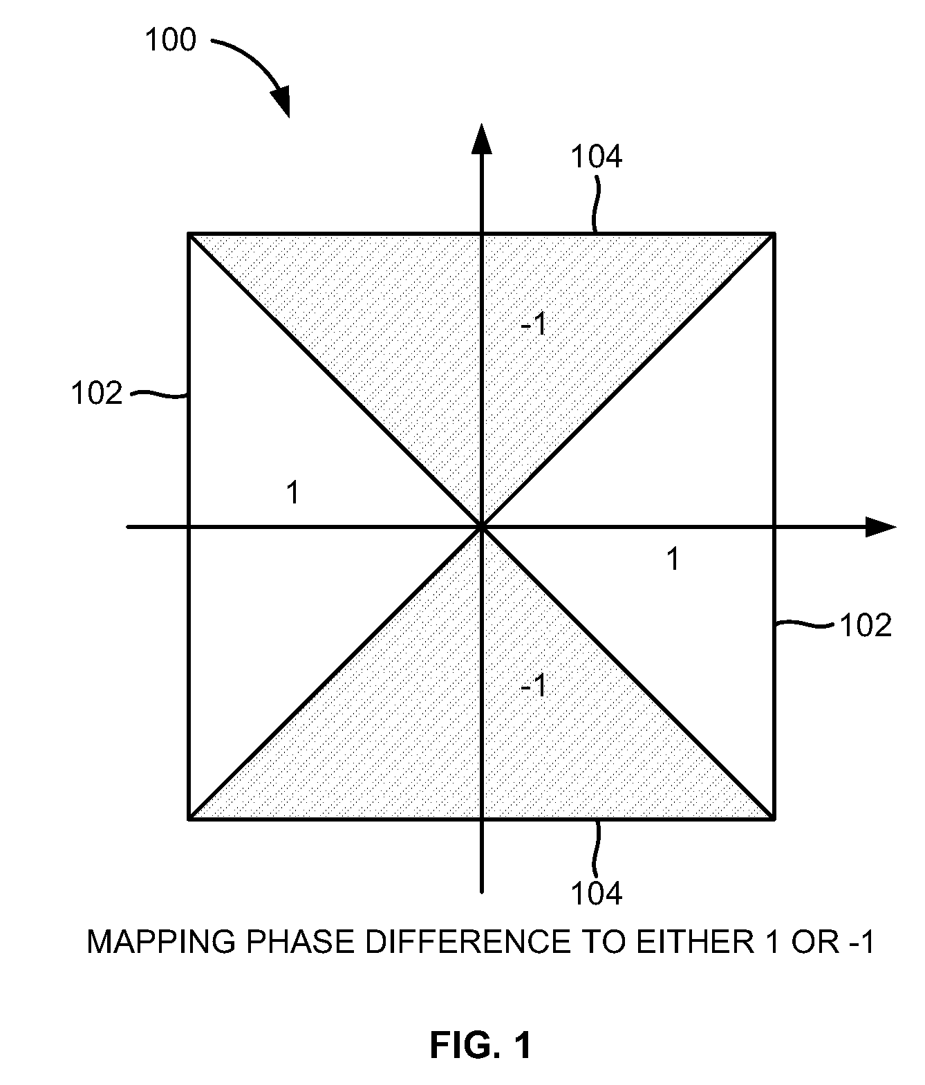
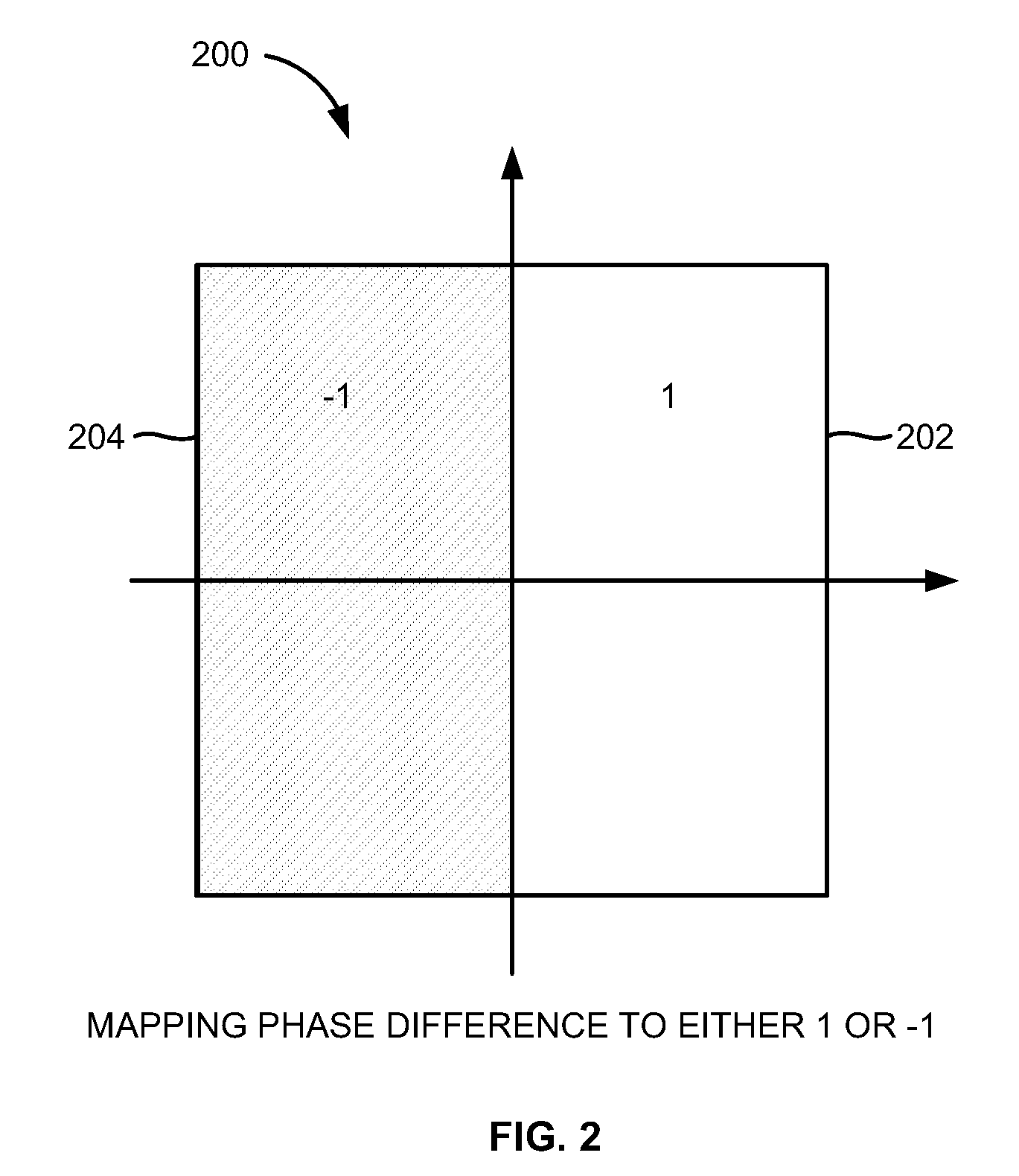
A method of estimating a coarse frequency offset in a receiver includes providing at least one candidate frequency offset in Orthogonal Frequency-Division Multiplexing (OFDM) symbols having transmission and multiplexing configuration control (TMCC) bins and auxiliary channel (AC) bins, modulating the TMCC bins and AC bins using differential binary phase shift keying (DBPSK) modulation, estimating a phase difference between a first symbol and a second symbol for the candidate frequency offset of the TMCC and AC bins to obtain a resulting phase difference, correcting the resulting phase difference based on a difference between the candidate frequency offset and a Fast Fourier Transform (FFT) center bin to obtain a corrected phase difference, mapping the corrected phase difference to numeric numbers, and adding the numeric numbers for the candidate frequency offset to obtain a summation result. The numeric numbers correspond to at least one of +1 or −1.

Description

BACKGROUND1. Technical FieldThe embodiments herein generally relate to wireless communication systems, and, more particularly, to coarse frequency offset estimation in wireless communication systems.2. Description of the Related ArtOrthogonal Frequency Division Multiplexing (OFDM) is a digital multi-carrier modulation scheme, which uses a large number of closely-spaced orthogonal sub-carriers. OFDM, because of its multiple advantages (e.g., high spectrum efficiency, resistance against multi-path interference, and ease of filtering out noise, etc.), has been widely used in wireless transmission technology such as terrestrial digital broadcasting. In a digital broadcasting receiver design such as Integrated Services Digital Broadcasting-terrestrial (ISDB-T) and Integrated Services Digital Broadcasting—terrestrial digital sound broadcasting (ISDB-TSB), the major disadvantage for OFDM systems is its impairment due to coarse frequency offset.Frequency offsets usually arise due to mismatc...

Claims


Application Information

Patent Timeline
Patent Type & Authority Patents(United States)
IPC IPC(8): H04L27/06
CPCH04L27/2659H04L27/2675H04L2027/0034H04L2027/0053H04L2027/0067
Inventor GU, YONGRUMA, JUN
Owner ATMEL CORP
Learn More