
Phosphor and manufacturing method therefore, and light emission device using the phosphor

a manufacturing method and technology of phosphor, applied in the direction of discharge tube luminescent screen, discharge tube/lamp details, luminescent composition, etc., can solve the problems of degrading the balance between the emission color of the phosphor and the emission element, short life span, and change of the tone of the white color, etc., to achieve excellent emission characteristics, improve luminance, and broad emission spectrum

Inactive Publication Date: 2011-11-22
MITSUBISHI CHEM CORP
View PDF14 Cites 17 Cited by
  • Summary
  • Abstract
  • Description
  • Claims
  • Application Information

AI Technical Summary

Benefits of technology

"The present invention proposes a new phosphor with excellent emission characteristics, including a flat excitation band, a broad emission spectrum, and high stability against heat. The phosphor has a unique structure and can be used in various emission devices to improve brightness, efficiency, and color rendering properties. The technical effects of the invention include improving the brightness and overall color rendering properties of LEDs and other emission devices that use the phosphor. The invention also addresses the problem of reducing the brightness and changing the color of the emitted light when using a combination of different phosphors."

Problems solved by technology

At present, a discharge type fluorescent lamp and an incandescent bulb used as the illumination device involve problems that a harmful substance such as mercury is contained, and life span is short.
For this reason, there is a problem in that the balance between the emission color of the phosphor and the emission element is degraded and the tone of the white color is changed.
On the other hand, a light emitting scheme that uses UV or near UV LED has a problem in that the emission intensity is dramatically reduced at temperatures of 100° C. or higher in the same manner as in a case in which ZnS:Cu, Al; (Sr, Ca)GaS:Eu; or another sulfurous phosphor having good light-emission characteristics is used as the phosphor.
However, there are problems with Ca-sialon-based phosphors in that the emission efficiency of the phosphor is insufficient in comparison with a YAG:Ce phosphor, and since the half-value width is narrow, adequate brightness and color rendering properties cannot be obtained except at a specific color temperature, a plurality of phosphors must be mixed to obtain an emission device that has excellent color rendering properties, and the overall emission characteristics as an emission device are thereby reduced.
However, these have poor emission efficiency, and are blue phosphors having a wavelength of 450 nm to 500 nm or red phosphors having a wavelength of 630 nm to 640 nm.

Method used


Image

  • Phosphor and manufacturing method therefore, and light emission device using the phosphor
  • Phosphor and manufacturing method therefore, and light emission device using the phosphor
  • Phosphor and manufacturing method therefore, and light emission device using the phosphor

Examples


first embodiment

Phosphor

[0085]A first phosphor of this embodiment is the phosphor having a matrix composition given by a general formula expressed by MmAaBbOoNn:Z. Here, element M is one kind of element or more selected from elements having bivalent valency in the phosphor. Element A is one kind of element or more having trivalent valency, element B is one kind of element or more having tetravalent valency, O is oxygen, N is nitrogen, and element Z is an element acting as the activator in the phosphor and is one kind of element or more selected from rare earth elements or transitional metal elements.

[0086]Also, in the phosphor, (a+b) / m satisfies the inequality 4.0o; a / m satisfies the inequality 0.5

[0087]The phosphor of the present invention having the first configuration described above according to this embodiment is a phosphor that has a flat excitation band in t...

Phosphor

[0140]A second phosphor according to this embodiment is a phosphor having a matrix structure expressed in the general formula (M(1)m(1)M(2)m(2)Zz)AaBbOoNn. In the formula, M(1) is one or more types of elements selected from elements having univalent valency in the phosphor, and M(2) is one or more types of elements selected from elements having bivalent valency in the phosphor. The element A is one or more types of elements selected from elements having trivalent valency in the phosphor. The element B is one or more types of elements selected from elements having tetravalent valency in the phosphor. O is oxygen. N is nitrogen. The element Z is an element that acts as an activator in the phosphor and is one or more types of elements selected from rare-earth elements or transition metal elements.

[0141]In the crystal structure of the phosphor, the M(1) element, the M(2) element, and the Z element are in the same atomic sites. Therefore, the crystal structure of the phosphor is ...

examples

[0210]The present invention will be described in greater detail below using examples.

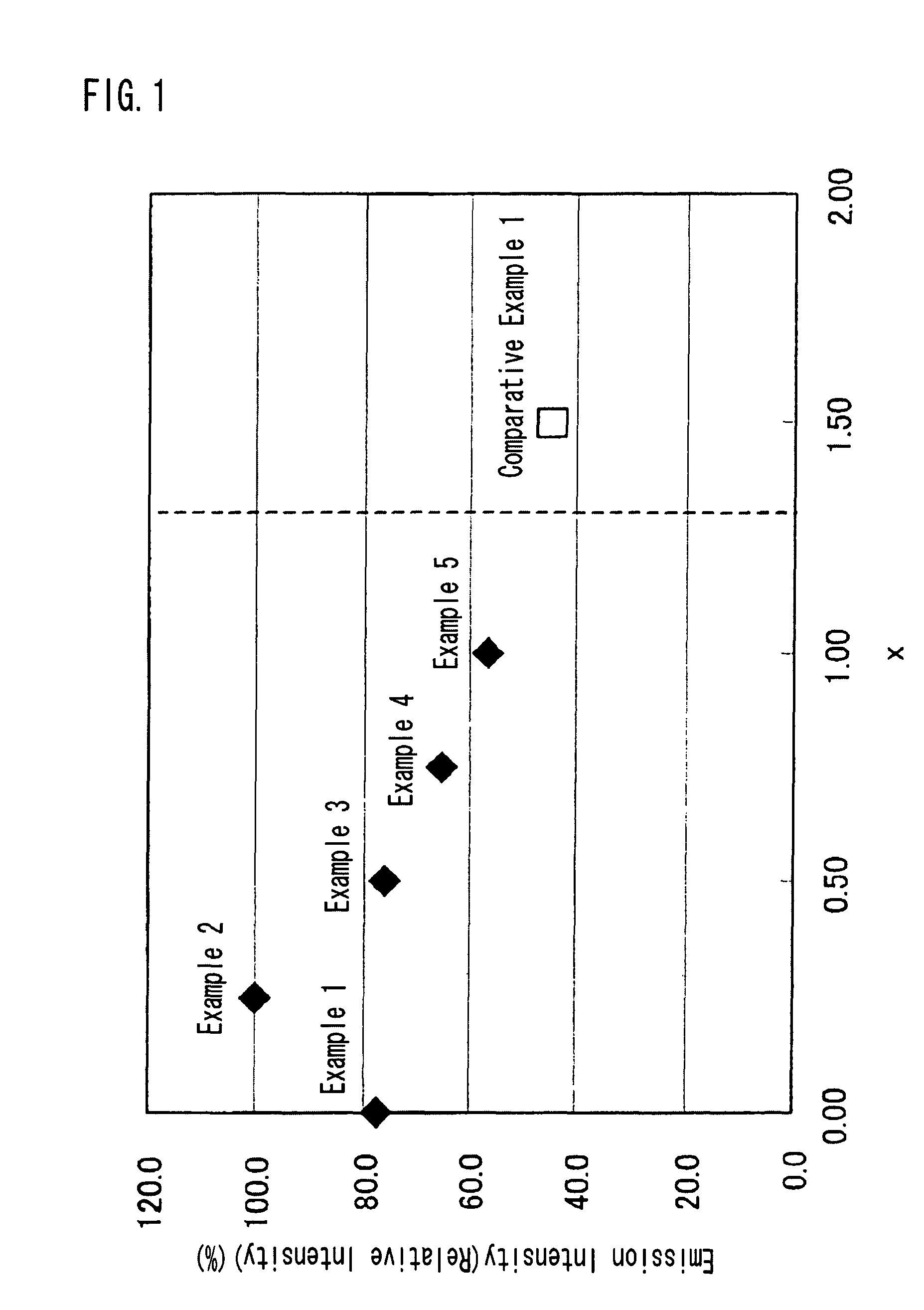
[0211]Examples 1 to 44 and comparative example 1 relate to the phosphor according to the first embodiment, and examples 45 to 65 and comparative examples 2 to 4 relate to the phosphor according to the second embodiment.


PUM

PropertyMeasurementUnit
peak wavelengthaaaaaaaaaa
molar ratioaaaaaaaaaa

Abstract

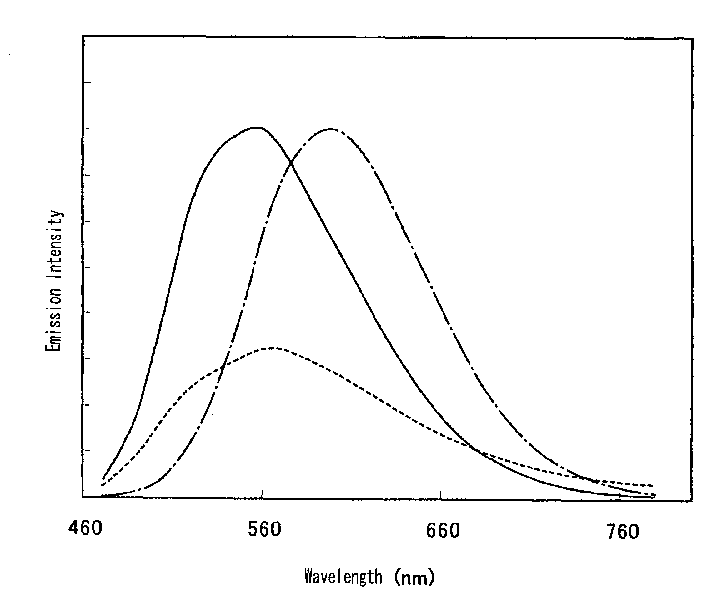
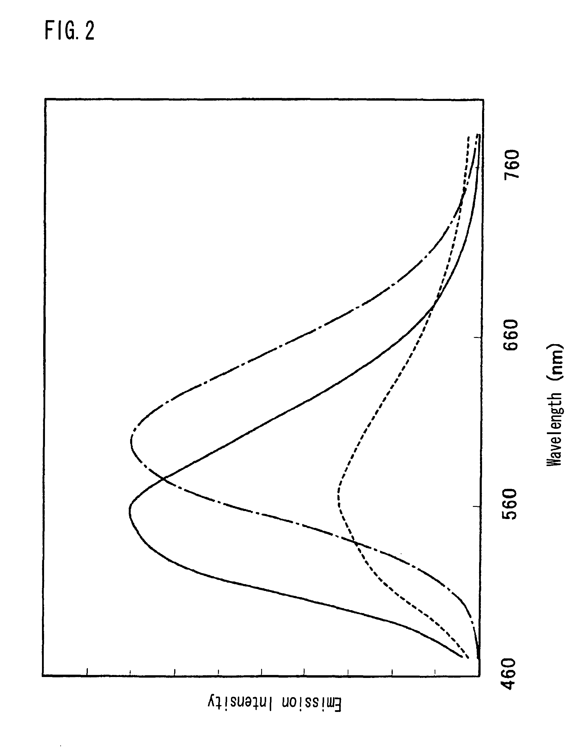
To provide a phosphor for manufacturing an one chip type LED illumination, etc, by combining a near ultraviolet / ultraviolet LED and a blue LED, and having an excellent emission efficiency including luminance. The phosphor is given as a general composition formula expressed by MmAaBbOoNn:Z, (where element M is one or more kinds of elements having bivalent valency, element A is one or more kinds of elements having tervalent valency, element B is one or more kinds of elements having tetravalent valency, O is oxygen, N is nitrogen, and element Z is one or more kinds of elements acting as an activator.), satisfying a=(1+x)×m, b=(4−x)×m, o=x×m, n=(7−x)×m, 0≦x≦1, wherein when excited by light in a wavelength range from 300 nm to 500 nm, the phosphor has an emission spectrum with a peak wavelength in a range from 500 nm to 620 nm.

Description

TECHNICAL FIELD OF THE INVENTION[0001]The present invention relates to a phosphor containing nitrogen used for a cathode-ray tube (CRT), a display such as a field emission display (FED) and a plasma display (PDP), and an illumination device such as a fluorescent lamp and a fluorescent display tube, and an illumination device such as a crystal liquid back light and a method of manufacturing therefore, and also to a light emission device such as a white LED illumination in which a phosphor mixture, a phosphor sheet, a semiconductor light emitting element (LED) and this phosphor are combined.BACKGROUND OF THE INVENTION[0002]At present, a discharge type fluorescent lamp and an incandescent bulb used as the illumination device involve problems that a harmful substance such as mercury is contained, and life span is short. However, in recent years, a high luminescence LED emitting light of near ultraviolet / ultraviolet to blue color has been developed in sequence, and the white LED illumina...

Claims


Application Information

Patent Timeline
Patent Type & Authority Patents(United States)
IPC IPC(8): H01L33/00C09K11/78C09K11/79C09K11/66C09K11/62C09K11/64H01L33/50
CPCC09K11/0883C09K11/643C09K11/7706C09K11/7721C09K11/7734C09K11/7739C09K11/7774C09K11/7792H01L33/502H05B33/14H01L2924/0002H01L2924/00C09K11/77928C09K11/77218C09K11/77348H01L33/00
Inventor NAGATOMI, AKIRASAKANE, KENJIYAMADA, TOMOYA
Owner MITSUBISHI CHEM CORP
Learn More