
Method for planarization of wafer and method for formation of isolation structure in top metal layer

a technology of isolation structure and planarization process, which is applied in the direction of crystal growth process, after-treatment details, instruments, etc., can solve the problems of difficult to meet the requirement for intense distribution of components by single-layer routing, and uneven surface of wafer, so as to improve the display quality of lcos lcd, ensure the surface flatness of the wafer, and improve the display quality

Active Publication Date: 2011-11-15
SEMICON MFG INT (SHANGHAI) CORP
View PDF9 Cites 10 Cited by
  • Summary
  • Abstract
  • Description
  • Claims
  • Application Information

AI Technical Summary

Benefits of technology

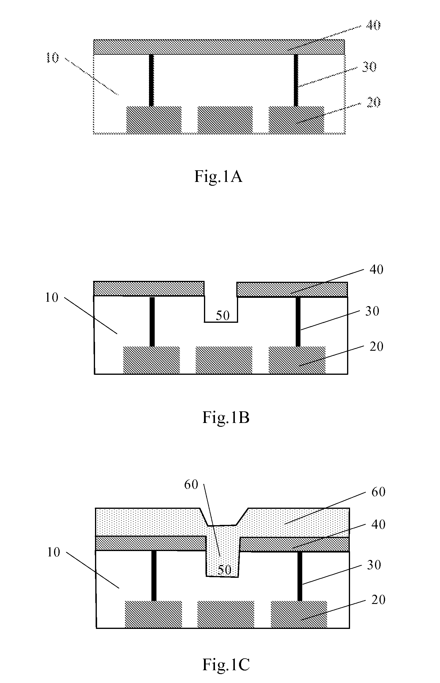
The present invention provides a method for planarization of a wafer surface with recesses after a planarization process. The method involves forming an etching-resist layer to fill the recesses, etching the surface layer and the etching-resist layer, and removing the etching-resist layer in the recess. The method ensures that the surface layer outside the recess is not higher than the bottom of the recess, and can be used to planarize a top metal layer on an insulating oxide layer with recesses. The method also includes a process of patterning the etching-resist layer, if necessary. The invention provides a solution to the problem of poor wafer surface quality after planarization.

Problems solved by technology

With the rapid development of Ultra Large Scale Integration (ULSI) technique, integrated circuits (ICs) manufacturing techniques become more and more complex and precise.
Therefore, it is difficult to meet the requirement for intense distribution of components by single-layer routing; multi-layer routing technique has been employed to utilize vertical space in a chip so as to further improve the integration degree of device.
However, the multi-layer metallization results in unevenness on the surface of the wafer and is severely disadvantage for patterning.
Now, Chemical Mechanical Polishing (CMP) is a commonly planarization method in wafer planarization process; however, latest investigations show that, the wafer surface flatness achieved by a conventional CMP can't meet the requirement for some applications, such as an application in optical instruments, an application in image transmission or image processing components and other products with a high requirement for surface quality, and the yield of the products is very low, due to the extremely high requirement for wafer surface flatness.
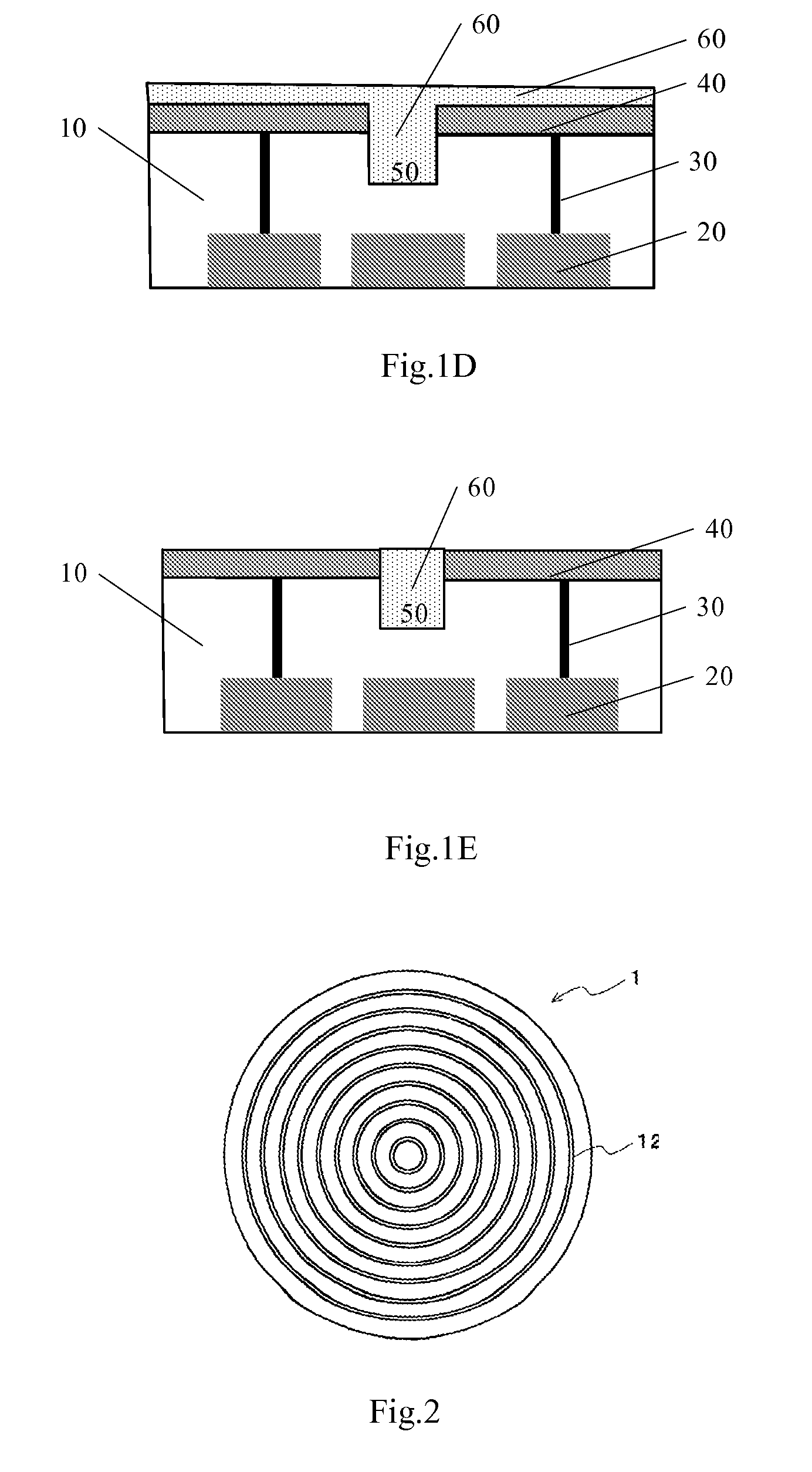
However, by means of a microscopic surface analysis, it is found that the top metal layer 40 formed by the above method has concentric ring recesses on the surface, as shown in FIG. 2, which causes the top metal layer 40 unable to be used as the mirror of LCOS.

Method used


Image

  • Method for planarization of wafer and method for formation of isolation structure in top metal layer
  • Method for planarization of wafer and method for formation of isolation structure in top metal layer
  • Method for planarization of wafer and method for formation of isolation structure in top metal layer

Examples


embodiment 1

[0063]The present invention provides a method for planarization of a wafer having a surface layer with recesses, comprising: forming an etching-resist layer on the surface layer to fill the recess and the thickness of the etching-resist layer in the recess is larger than that outside the recess; etching the etching-resist layer and the surface layer; wherein, the etching speed of the surface layer is higher than that of the etching-resist layer, so that the portions of the surface layer outside the recess will not be higher than the bottom of recess after etching; and removing the etching-resist layer.

[0064]As shown in FIG. 4A, a wafer having a semiconductor substrate 100 is provided; the semiconductor substrate 100 may be applied to semiconductor manufacturing processes, and may have devices and circuits formed therein. Due to the fact that different devices and circuits may be contained in different structures depending on the specific manufacturing processes, the internal structu...

embodiment 2

[0072]The present invention also provides a method for planarization of a top metal layer in LCOS, wherein the top metal layer is contained in a wafer and includes a trench and an insulating oxide layer including a recess formed over the trench and the top metal layer, a position of the recess in the insulating oxide layer corresponding to the trench; the method comprises the following steps: forming an etching-resist layer over the insulating oxide layer to fill the recess, the thickness of the etching-resist layer in the recess being larger than that outside the recess; etching the etching-resist layer and the insulating oxide layer, wherein the etching speed of the insulating oxide layer is higher than that of the etching-resist layer, so that the insulating oxide layer outside the recess will not be higher than the bottom of the recess; removing the etching-resist layer; and etching the insulating oxide layer till the top metal layer is exposed completely.

[0073]As shown in FIG. ...

embodiment 3

[0081]The present invention also provides a method for planarization of a top metal layer in LCOS, wherein a wafer having an ILD layer and a top metal layer formed over the ILD layer is provided, the method comprising the following steps: etching the top metal layer and the ILD layer to a predetermined depth, to form a trench in the top metal layer and the ILD layer; forming an insulating oxide layer over the top metal layer and the trench so as to fill the trench, the insulating oxide layer having a recess at a position corresponding to the trench; forming an etching-resist layer over the insulating oxide layer to fill the recess, and a thickness of the etching-resist layer in the recess is larger than that outside the recess; etching the etching-resist layer and the insulating oxide layer, the etching speed of the insulating oxide layer being higher than that of the etching-resist layer, so that the insulating oxide layer outside the recess will not be higher than the bottom of th...


PUM

PropertyMeasurementUnit
thicknessaaaaaaaaaa
flatnessaaaaaaaaaa
insulatingaaaaaaaaaa

Abstract

The invention discloses a planarization method for a wafer having a surface layer with a recess, comprises: forming an etching-resist layer on the surface layer to fill the entire recess; etching the etching-resist layer and the surface layer, till the surface layer outside the recess is flush to or lower than the bottom of the recess, the etching speed of the surface layer being higher than that of the etching-resist layer; removing the etching-resist layer; and etching the surface layer to a predetermined depth. The method can avoid concentric ring recesses on the surface of the wafer resulted from a chemical mechanical polishing (CMP) process in the prior art, and can be used to obtain a wafer surface suitable for optical applications.

Description

[0001]This application claims the priority of Chinese Patent Application No. 200610116853.7, filed Sep. 30, 2006, the entire disclosure of which is incorporated herein by reference.FIELD OF THE INVENTION[0002]The present invention relates to a planarization process in semiconductor manufacturing, particularly to a method for planarization of a wafer and a method for forming an isolation structure in a top metal layer in Liquid Crystal on Silicon (LCOS) technique.BACKGROUND OF THE INVENTION[0003]With the rapid development of Ultra Large Scale Integration (ULSI) technique, integrated circuits (ICs) manufacturing techniques become more and more complex and precise. In order to improve an integration degree and reduce a manufacturing cost of a device, the Feature Size of components becomes smaller and smaller, and the number of components per unit area in a chip becomes higher and higher. Therefore, it is difficult to meet the requirement for intense distribution of components by single...

Claims


Application Information

Patent Timeline
Patent Type & Authority Patents(United States)
IPC IPC(8): H01L21/311H01B13/00C30B33/00B44C1/22
CPCG02F1/133553G02F1/136277G02F2201/48
Inventor HUANG, HERB HEPU, XIANYONGHAN, YI'NANCHEN, YIQUN
Owner SEMICON MFG INT (SHANGHAI) CORP
Learn More