Toner

a technology of toner and smearing, applied in the field of toner, can solve the problems of hardly shaved and hardly refreshed latent image bearing members, inability to inhibit the occurrence of image defects with reliability, and inability to improve the prevention of image smearing, etc., to prevent the occurrence of image defects, improve the charging stability, and not deteriora

Inactive Publication Date: 2011-11-15
CANON KK
View PDF15 Cites 27 Cited by
  • Summary
  • Abstract
  • Description
  • Claims
  • Application Information

AI Technical Summary

Benefits of technology

[0018]Another object of the present invention is to provide a toner capable of providing stable image quality without causing any image defect even when the toner is used over a long time period in a high-speed developing system.
[0020]According to a preferred embodiment of the present invention, there can be provided a toner capable of showing the following characteristics in a high-speed developing system for a long time period: the toner prevents the occurrence of image defects such as image smearing, is excellent in charging stability, does not deteriorate, and provides a stable image density.

Problems solved by technology

However, when the durability of the electrostatic latent image bearing member is improved as described above so that the electrostatic latent image bearing member can be used in a POD application, the surface of the electrostatic latent image bearing member is hardly shaved and hardly refreshed, so the improvement is disadvantageous for the prevention of image smearing.
However, it has been demanded to perform the removal of the drum heater for energy-saving purposes because the drum heater requires electrification and consumes power even at nighttime during which the drum heater is not used.
In addition, even when such a constitution that corona products on the electrostatic latent image bearing member are removed with an air blow or the like is established, an increase in amount of the corona products to be produced precludes sufficient removal of the products, so it may become impossible to inhibit the occurrence of an image defect with reliability.
However, when the approach is employed in the above-mentioned POD application, an electrostatic latent image bearing member is hardly abraded, with the result that corona products cannot be sufficiently removed.
In addition, when fine particles each of which can serve as a spacer are added to the toner, a phenomenon in which the spacer particles are liberated occurs, so image defects due to the contamination of the inside of the apparatus and insufficient charging of the member are prompted in some cases.
However, it is hard to say that the compound has a sufficient adsorbing ability because the sites where the ions can substitute are mainly the edge portions of the respective layers.
However, zeolite as a porous material has a pore diameter as small as about 1.5 nm, and a wall between a pore and an adjacent pore is thin, so zeolite has a low physical strength as a porous material.
Since toner is stirred at a high speed particularly in a developing device to be used in a POD application, the following detrimental effect arises: the shapes of porous external additive particles are broken by a sliding action between the particles, and the broken external additive particles affect the parent body of the toner.
As a result, there is a possibility that the pores cannot sufficiently exert their substituting abilities, and corona products cannot be sufficiently removed.
As a result, the powder serves as a liberated external additive particularly in a high-speed developing system to be used in a POD application, and the scattering of the powder may lead to the contamination of the inside of the system, or may cause the destabilization of the charging of the system.
However, the compound used has a large pore diameter, and cannot sufficiently capture corona products, so the proposal is not a sufficient measure against image smearing.
As described above, at present, no toner capable of achieving compatibility between the removal of a corona product and a combination of high durability and high stability in a high-speed developing system for a POD application using no drum heater is still available.

Method used


Image

  • Toner
  • Toner
  • Toner

Examples


example 1

[0185]

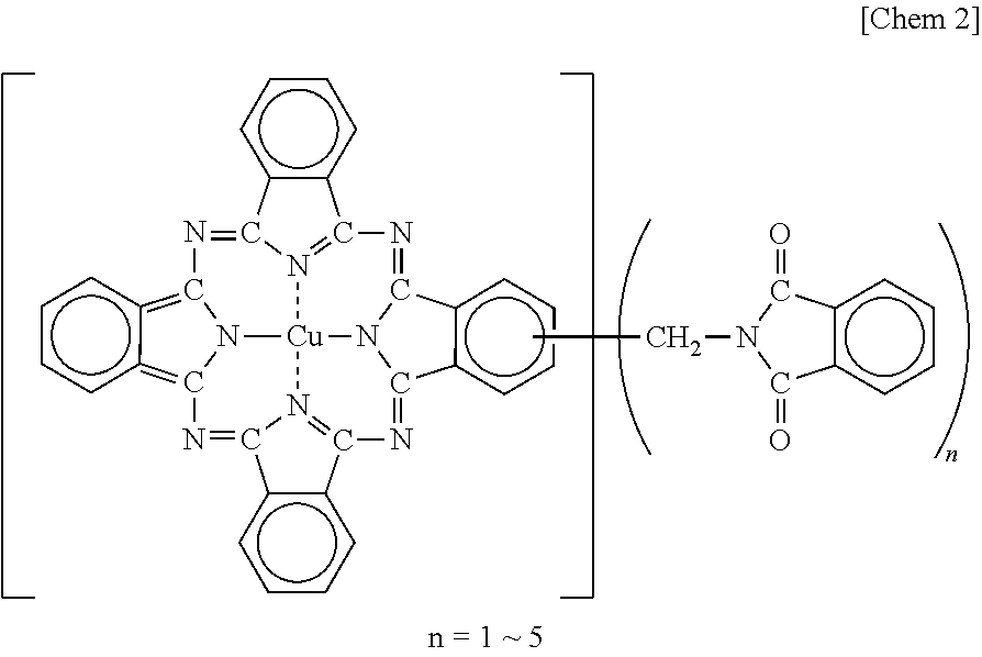
Binder Resin 1100 parts by massMagnetic iron oxide particles (average particle size 75 parts by massof 0.14 μm, Hc = 11.5 kA / m, σs = 90 Am2 / kg, σr =16 Am2 / kg)Wax (Fisher Tropsch Wax; melting point of 105° C.)  4 parts by massCharge control agent (structural formula I below) 2 parts by mass(Structural formula I)

[0186]The above-mentioned materials were premixed by using a Henschel mixer. After that, the mixture was melted and kneaded by using a biaxial kneading extruder. At this time, a residence time was controlled in such a manner that the temperature of the kneaded resin would be 150° C. The resultant kneaded product was cooled and coarsely ground by using a hammer mill. After that, the coarsely ground product was ground by using a turbo mill, and the resultant finely ground powder was classified by using a multi-division classifier utilizing a Coanda effect, whereby toner particles having a weight average particle diameter of 6.0 μm were obtained.

[0187]1.00 part by mass of a...

examples 2 to 18

[0194]Toners 2 to 18 were each obtained in the same manner as in Example 1 except that a prescription shown in Table 4 was adopted. In addition, Tables 4 to 6 show the results of tests similar to those of Example 1 carried out on the toners.


PUM

PropertyMeasurementUnit
pore diameteraaaaaaaaaa
specific surface areaaaaaaaaaaa

Abstract

Provide is a toner including toner particles each containing at least a binder resin and a colorant, and an inorganic fine powder, in which the inorganic fine powder has a ratio (A / B) of a total pore volume A measured in a pore diameter range of from 1.9 nm or more and to 8.0 nm or less to a total pore volume B measured in a pore diameter range of from 1.9 nm or more and to 300.0 nm or less of from 0.20 or more and to 1.00 or less, and the total pore volume A is from 1.00×10⁻² cm3 / g or more and to 1.00 cm3 / g or less.

Description

BACKGROUND OF THE INVENTION[0001]1. Field of the Invention[0002]The present invention relates to a toner to be used in an image-forming method or toner jet method for visualizing an electrostatic image in electrophotography.[0003]2. Description of the Related Art[0004]An electrophotographic method involves: charging an electrostatic latent image bearing member composed of a photoconductive substance by various means; exposing the charged electrostatic latent image bearing member to light to form an electrostatic latent image on the surface of the electrostatic latent image bearing member; developing the electrostatic latent image with toner to form a toner image; transferring the toner image onto a transfer material such as paper; and fixing the toner image on the transfer material with one or both of heat and pressure to provide a copied article or print.[0005]When such image-forming process is repeated a large number of times, ozone produced in the charging step of charging the el...

Claims


Application Information

Patent Timeline
Patent Type & Authority Patents(United States)
IPC IPC(8): G03G9/08
CPCG03G9/09708G03G9/09716G03G9/09725
Inventor MORIBE, SYUHEIYAMAZAKI, KATSUHISAYOSHIBA, DAISUKEFUJIMOTO, MASAMI
Owner CANON KK
Why Eureka
Try Eureka