Fundus imaging apparatus

a technology of imaging apparatus and microscope, which is applied in the field offundus imaging apparatus, can solve the problems of difficult to image such fine biological materials in an observable sta

Active Publication Date: 2011-11-15
NIDEK CO LTD
View PDF9 Cites 5 Cited by
  • Summary
  • Abstract
  • Description
  • Claims
  • Application Information

AI Technical Summary

Problems solved by technology

It is therefore difficult to image such fine biological materials in an observable state.

Method used


Image

  • Fundus imaging apparatus
  • Fundus imaging apparatus
  • Fundus imaging apparatus

Examples


Embodiment Construction

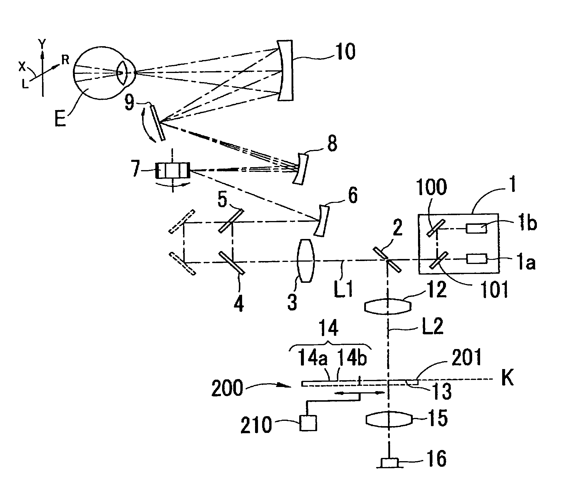
[0022]A detailed description of a preferred embodiment of the present invention will now be given referring to the accompanying drawings. FIG. 1 is a diagram showing an optical system of a fundus imaging apparatus in this embodiment. In the following explanation, an X-direction represents right and left direction and a Y-direction represents up and down direction. The right (R) direction indicates a right-hand direction of the apparatus when an examinee is seen from the apparatus facing the examinee and the left (L) direction indicates a left-hand direction of the apparatus when the examinee is seen from the apparatus facing the examinee.

[0023]Numeral 1 is a laser beam emission part capable of emitting a laser beam of a first wavelength and a laser beam of a second wavelength. This emission part 1 includes a first laser source 1a that emits a laser beam having a wavelength in an infrared region, a second laser source 1b that emits a laser beam having a wavelength in a visible range,...


PUM


Abstract

A fundus imaging apparatus comprises: an irradiation optical system comprising a light source which emits a laser beam and a scanner which two-dimensionally scans the laser beam on a fundus of an examinee's eye, the irradiation optical system being adapted to focus the laser beam emitted from the light source on the fundus to form a confocal region; an imaging optical system comprising a photo-receiving element which receives reflection light of the laser beam reflected from the fundus, the imaging optical system being adapted to focus the reflection light from the fundus and receive the reflection light by the photo-receiving element; and a beam restriction member placed in an optical path of the imaging optical system, the beam restriction member comprising: one of an opening through which part of the reflection light from the fundus outside the confocal region is allowed to pass toward the photo-receiving element and a mirror part which reflects the part of the reflection light from the fundus outside the confocal region toward the photo-receiving element; and a light shielding part which shields the reflection light from the fundus in the confocal region and the part of the reflection light from the fundus outside the confocal region. The light shielding part includes a first light shielding part placed in a conjugate position with a focus point of the laser beam on the fundus and a second light shielding part placed in a nearly conjugate position with the fundus and adapted to shield part of an optical path of the reflection light, the second light shielding part is formed around the first light shielding part.

Description

BACKGROUND OF THE INVENTION[0001]1. Field of the Invention[0002]The present invention relates to a fundus imaging apparatus for imaging a fundus of an examinee's eye to observe the fundus.[0003]2. Description of Related Art[0004]There is a known fundus imaging apparatus arranged to two-dimensionally scan a laser beam across a fundus, and receive reflection light therefrom to produce a fundus image. For such fundus imaging apparatus, a technique (Scattered Light Imaging) has been known in which a ring aperture including a ring-shaped opening and a black-spot plate is placed in conjugate relation with a fundus of an examinee's eye to restrict reflection light from a light condensing point (a focus point) on a portion under observation, the method including receiving scattered light from front and back of the light condensing point to create an image (see JP2007-89828A).[0005]In the case of conventional scattered light imaging, meanwhile, scattered light coming from front and back of t...

Claims


Application Information

Patent Timeline
Patent Type & Authority Patents(United States)
IPC IPC(8): A61B3/14
CPCA61B3/1025A61B5/0068
Inventor AKITA, JUNICHIYOSHIDA, AKITOSHIISHIKO, SATOSHI
Owner NIDEK CO LTD
Why Eureka
Try Eureka