Hydraulic piston pump with a balance valve

a technology of balance valve and hydraulic piston, applied in the direction of machines/engines, liquid fuel engines, positive displacement liquid engines, etc., can solve the problems of pulsating pressure, noise, vibration and noise, and/or bubbles, so as to prevent pulsating of pressure oil and reduce noise and vibration

Inactive Publication Date: 2011-11-01
KOMATSU LTD
View PDF32 Cites 6 Cited by
  • Summary
  • Abstract
  • Description
  • Claims
  • Application Information

AI Technical Summary

Benefits of technology

In the present invention, before the cylinder bore communicates with the oil guiding groove or the oil guiding tube or the timing hole of the discharge port, the balance piston is activated in response to the pressure difference between the chamber pressure in the cylinder bore and the system pressure in the discharge port. With this actuation of the balance piston, the chamber pressure can be equilibrated to the system pressure.
Further, when the cylinder bore communicates with the discharge port, the chamber pressure and the system pressure are in an equilibrium condition. This makes it possible to prevent pulsating of pressure oil from occurring between the cylinder bore and the discharge port, and to reduce generation of noise and vibration in the hydraulic piston pump.

Problems solved by technology

Due to this pressure difference, backflow of pressure oil from the discharge port into the cylinder bore occurs to generate bubbles, pulsating pressure, and / or noise.
Thus, when the system pressure is high, the high pressure oil enters the cylinder bore from the hole 71 to prevent the operation of the piston in the cylinder bore and to generate fine bubbles in the cylinder bore or pulsating pressure, thereby causing vibration and noise.

Method used


Image

  • Hydraulic piston pump with a balance valve
  • Hydraulic piston pump with a balance valve
  • Hydraulic piston pump with a balance valve

Examples


first embodiment

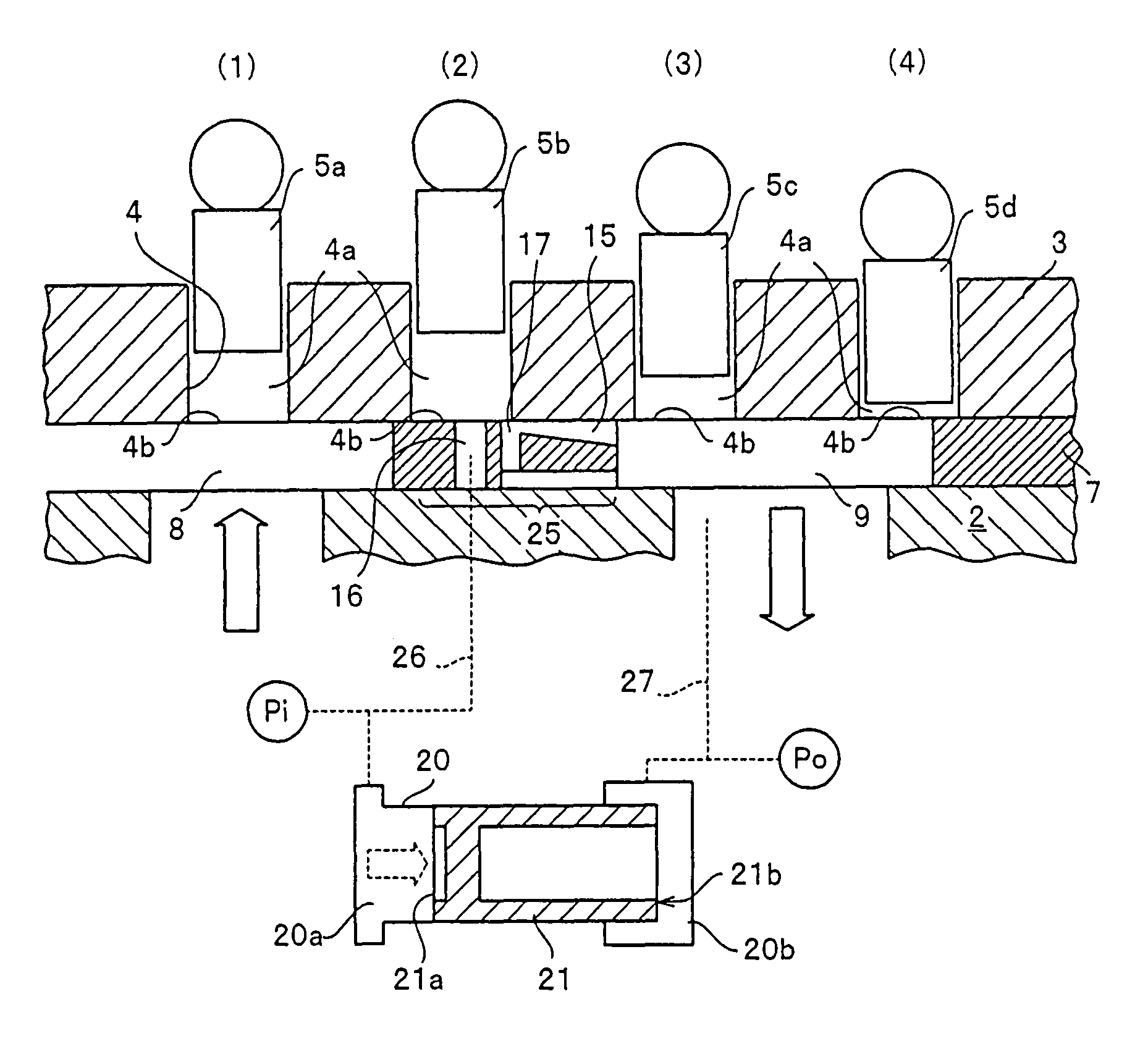
FIG. 1 is a view showing a constitution of a hydraulic piston pump in order to describe a constitution with a characteristic of the present invention. FIG. 1 shows one example of a cam plate type axial piston pump which has been conventionally used. A hydraulic piston pump 1 has a rotation shaft 6 rotatably supported on a casing 2 through a bearing and a cylinder block 3 rotatably supported on the casing 2. The cylinder block 3 rotates integrally with the rotation shaft 6 by means of a spline 13, a key groove, or the like.

A plurality of cylinder bores 4 are formed on a single circumference whose center corresponds to the rotation axis in the cylinder block 3, and a piston 5 is slidably fitted into each cylinder bore 4. An end surface of the cylinder block 3 is slidably in contact with a surface of a valve plate 7. A shoe 11 is rotatably attached to the distal end of the piston 5 which slides inside the cylinder bore 4, and the shoe 11 can slide on a cam plate 10 while its sliding di...

second embodiment

FIG. 7 shows a block diagram in which a spring is arranged in order to return the balance piston of the balance valve to an initial position and in which a timing hole is not formed on the valve plate 7. A second embodiment shows a modified example of the balance valve 20. In the second embodiment, the constitution in which a spring is arranged inside the balance valve 20 in order to return the balance piston to the initial position is provided, and it is different from the constitution of the balance valve 20 of the first embodiment.

The constitution of the second embodiment has a constitution similar to that of the first embodiment other than that in which the timing hole is not formed on the valve plate 7. The constitution in which a spring is arranged in order to return the balance piston 21 to the initial position will be mainly described below. With respect to constituent members other than the balance valve 20, the same reference numerals as those employed in the first embodim...

third embodiment

FIG. 10 is a block diagram showing an example in which the through hole 16 is formed on a portion on which it communicates with the cylinder port 4b when the piston 5 becomes immediately before the bottom dead center. FIG. 9 is also employed for supporting explanation, since a principal part view obtained by viewing the arrangement relationship on the plane surface of the valve plate 7 corresponds to views similar to FIG. 9 in the second embodiment.

A third embodiment has a constitution in which a spring is not arranged in the balance valve 20 as shown in FIG. 10, which is different from the balance valve 20 shown in FIG. 7 of the second embodiment. That is, in the second embodiment, as shown in FIGS. 7 and 8, as a constitution for returning the balance piston 21 to the initial position, provided is the constitution in which the spring 23 is arranged in the second pressure chamber 20b or the constitution in which the area difference in pressure receiving areas of the balance piston 2...


PUM


Abstract

In a hydraulic piston pump, a cylinder port can communicate with a discharge port after a system pressure and a chamber pressure in a cylinder bore becomes in an equilibrium condition. A through hole opening to a surface on which a cylinder block slides in a valve plate is allowed to communicate with a side of one end surface of a balance valve, and the system pressure of a discharge port side is supplied to the other end surface of the balance valve. In the balance valve, a balance piston which slides by a pressure difference between the chamber pressure of the cylinder bore and the system pressure is accommodated. Before the cylinder port communicates with an oil guiding groove, the chamber pressure can be equilibrated to the system pressure by an activation of the balance piston.

Description

TECHNICAL FIELDThe present invention relates to a hydraulic piston pump.BACKGROUND ARTConventionally, as a hydraulic piston pump, an axial piston pump has been widely employed as a fixed capacity type pump or a variable capacity type pump.In general, in a hydraulic piston pump, oil is, in an absorption process, absorbed from an absorption port of a valve plate into a cylinder bore through a cylinder port of a cylinder bore formed in a cylinder block. Further, in a discharge process, pressure oil in the cylinder bore is discharged into a discharge port of the valve plate through a cylinder port. The discharged pressure oil is supplied to a hydraulic pressure system having a specific system pressure, an actuator, or the like.In an area in which the cylinder port is switched from the absorption port to the discharge port, a chamber pressure of the cylinder bore is an absorption pressure until the time when the cylinder port is at a position corresponding to a bottom dead center of a pi...

Claims


Application Information

Patent Timeline
Patent Type & Authority Patents(United States)
IPC IPC(8): F01B3/02F01B3/10F04B1/12F04B11/00
CPCF04B1/2021F04B1/2042
Inventor SHINOHARA, SHIGERUARAI, MITSURU
Owner KOMATSU LTD
Why Eureka
Try Eureka