Compressor

A compressor and compression mechanism technology, applied in the field of compressors, can solve problems such as compressor failure, high-pressure pipeline vibration, and abnormal noises, and achieve the effects of preventing abnormal noises and reliable operation

Active Publication Date: 2006-03-22
PANASONIC CORP
View PDF2 Cites 6 Cited by
  • Summary
  • Abstract
  • Description
  • Claims
  • Application Information

AI Technical Summary

Problems solved by technology

[0008] However, in the structure shown in JP-A-4-153596, since the space from the exhaust valve to the lubricating oil separator is narrow, the pressure fluctuation (pulsation pressure) of the exhaust gas discharged from the compression mechanism is not easily attenuated. , the high-pressure pipeline connected to the gas discharge port of the compressor will vibrate, causing the associated refrigeration cycle components (such as heat exchangers) and vehicle components to resonate, and it is easy to produce abnormal sounds (that is, pulsation sound)
[0009] In addition, with the vane back pressure control device described in the above-mentioned reference Japanese Patent Publication No. 7-45877, it is necessary to reliably supply gaseous fluid into the air supply channel especially when the compressor is started. If it is supplied to the air supply channel, it may cause the compressor to fail to work
[0010] In particular, in a compressor equipped with such a vane back pressure control device, since the vane back pressure control device is installed in the space where lubricating oil is stored, when performing maintenance such as replacing the compressor, if the wrong If more than the specified amount of lubricating oil is added, the oil level will rise above the specified position. In this way, the lubricating oil is likely to enter the device from the inlet of the air supply channel of the sliding vane back pressure control device when the compressor is started.

Method used


Image

  • Compressor
  • Compressor
  • Compressor

Examples


Embodiment Construction

[0027] Embodiments when the present invention is applied to a vane rotary compressor will be described below with reference to the drawings.

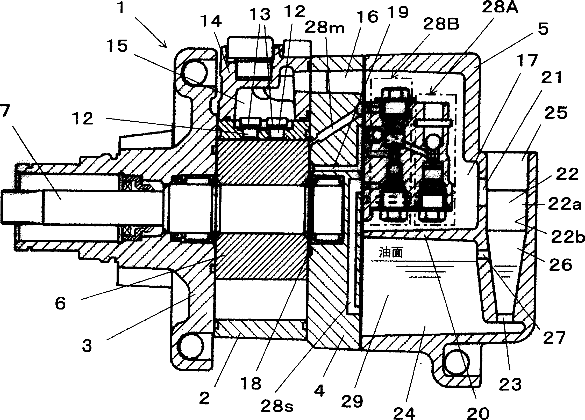
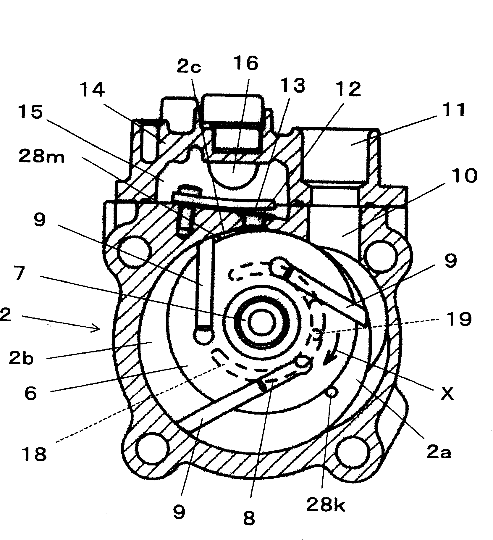
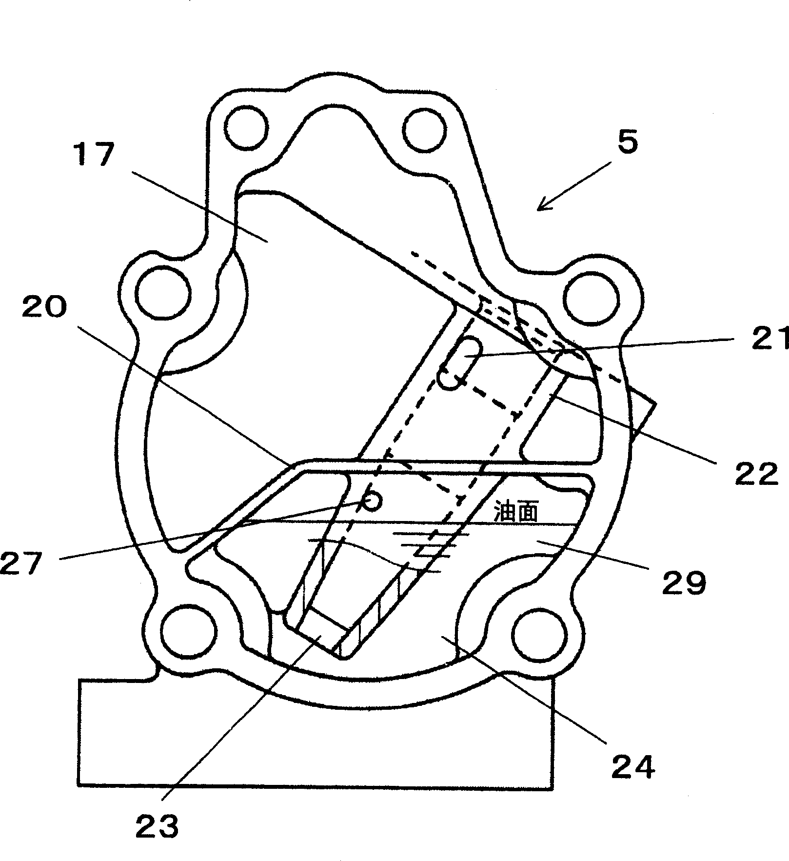
[0028] exist Figure 1 to Figure 4 Among them, reference symbol 1 is a compressor, which includes: a cylinder 2 with a cylindrical inner wall; a front side plate 3 and a rear side plate 4 that block the front and rear openings of the cylinder 2; and are arranged side by side with the rear side plate 4 The hyperbaric chamber (hereinafter also referred to as the hyperbaric chamber cover 5.

[0029] The interior of the cylinder 2 is installed with a substantially cylindrical rotor 6 that can rotate freely. The rotor 6 is eccentric with respect to the axis of the cylinder 2, and a small gap is formed between part of its outer periphery and the inner wall of the cylinder 2. . The rotor 6 is provided with a drive shaft 7 integrated therewith, and the drive shaft 7 is installed in the front side plate 3 and the rear side plate 4 through bear...


PUM


Abstract

The present invention provides one kind of sliding-vane rotary compressor. Inside the limited volume of high pressure compartment, the high pressure chamber is set to have volume greater than that of oil storing chamber to prevent resonance between the refrigerating circulation parts, such as the heat exchanger, and the relevant vehicle members and to avoid abnormal sound. The sliding-vane rotary compressor includes high pressure chamber for the compressed fluid to be exhausted into, oil storing chamber for the lubricant oil separated from the high pressure fluid to be stored in, and sliding vane back pressure controller to provide the sliding vane back pressure chamber with gaseous fluid or lubricant oil from the oil storing chamber optionally. By means of setting the sliding vane back pressure controller set inside the high pressure chamber, the present invention can ensure the volume of the high pressure chamber and the fluid supply from the high pressure chamber to the sliding vane back pressure controller.

Description

technical field [0001] The present invention relates to a compressor for compressing and discharging a fluid, and more particularly, to a compressor used in an automobile air conditioner and the like. Background technique [0002] In a general compressor installed in a vehicle air conditioner, a part of the compressor lubricating oil is discharged into the refrigeration cycle part of the air conditioner together with the fluid (refrigerant) compressed by the compression mechanism. [0003] The more compressor lubricating oil is discharged into the refrigerating cycle part together with the fluid (gas refrigerant), the lower the heat transfer efficiency of the heat exchanger in the refrigerating cycle part is. In addition, the pipe pressure loss in the refrigeration cycle components will also increase, and the efficiency of the refrigeration cycle will decrease. [0004] The existing method for solving the above problem is to install in the compressor: an oil storage chamber...

Claims


Application Information

Patent Timeline
Patent Type & Authority Applications(China)
IPC IPC(8): F04C29/06F04C18/344
Inventor 山本信之
Owner PANASONIC CORP
Why Eureka
Try Eureka