
Rubbing method, method of fabricating liquid crystal display device using the same, and liquid crystal display device manufactured thereby

a technology of liquid crystal molecules and rubbing cloths, which is applied in non-linear optics, instruments, optics, etc., can solve the problems of physical interference with the fibers of the rubbing cloth, reducing the alignment capability of the alignment layer which aligns the liquid crystal molecules, and reducing the alignment capability of the alignment layer. , to achieve the effect of reducing interference and minimizing the disclination region

Active Publication Date: 2011-10-25
LG DISPLAY CO LTD
View PDF2 Cites 22 Cited by
  • Summary
  • Abstract
  • Description
  • Claims
  • Application Information

AI Technical Summary

Benefits of technology

[0036]The liquid crystal display device according to the present invention offers an effect of minimizing a disclination region by reducing the interference between the pattern spacer formed on the substrate and the fibers of the rubbing cloth in the rubbing process.

Problems solved by technology

However, during the rubbing process, the patterns having height difference formed on the substrate physically interfere with the fibers of the rubbing cloth.
The physical interference causes difficulty when the alignment layer aligns the liquid crystal molecules.
When there is physical interference between the rubbing cloth and the various patterns, the alignment layer is not sufficiently rubbed, thereby reducing an alignment capability of the alignment layer which aligns the liquid crystal molecules.
Accordingly, the interference between the pattern spacer and the rubbing cloth becomes a main factor which reduces an alignment capability of the alignment layer.

Method used


Image

  • Rubbing method, method of fabricating liquid crystal display device using the same, and liquid crystal display device manufactured thereby
  • Rubbing method, method of fabricating liquid crystal display device using the same, and liquid crystal display device manufactured thereby
  • Rubbing method, method of fabricating liquid crystal display device using the same, and liquid crystal display device manufactured thereby

Examples


Embodiment Construction

[0053]Reference will now be made in detail to the preferred embodiments of the present invention, examples of which are illustrated in the accompanying drawings. Wherever possible, the same reference numbers will be used throughout the drawings to refer to the same or like parts.

[0054]Hereinafter, an embodiment of the present invention will be described in detail.

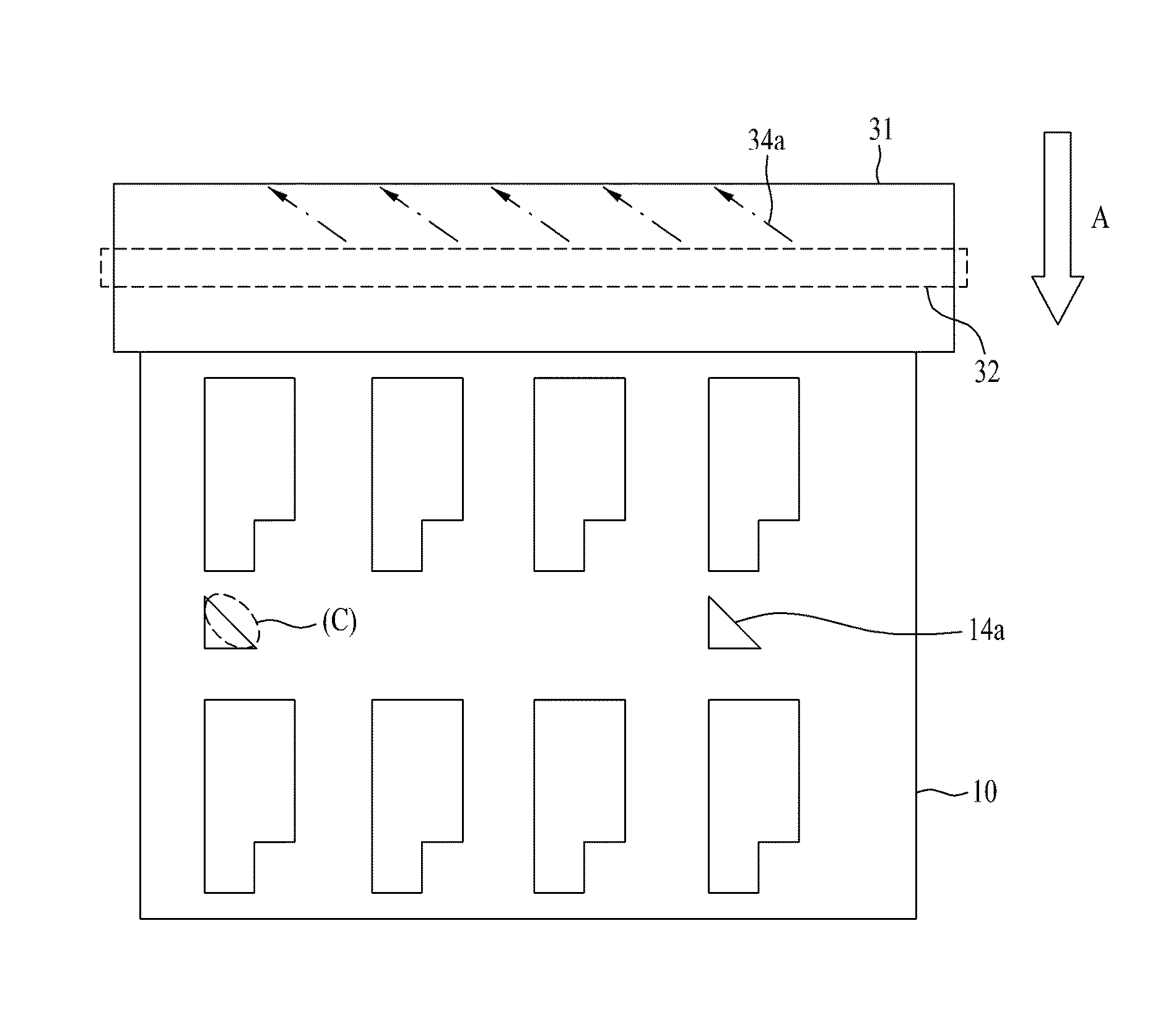
[0055]First, a rubbing method according to the embodiment of the present invention includes loading a substrate having an alignment layer on a stage, rotating a rubbing roll wrapped with a rubbing cloth having fibers inclined in a left or right direction with respect to a perpendicular direction of a rotation shaft, and rubbing the alignment layer while moving at least one of the rubbing cloth and the substrate.

[0056]The substrate includes a pattern spacer formed to be inclined in a direction parallel to an inclined direction of the fibers of the cloth.

[0057]Next, the rubbing method according to the embodiment of the presen...


PUM

PropertyMeasurementUnit
angleaaaaaaaaaa
angleaaaaaaaaaa
temperatureaaaaaaaaaa

Abstract

A liquid crystal display device capable of reducing a disclination region generated when an alignment layer is not normally rubbed due to physical interference between a pattern spacer formed on a substrate and fibers of a rubbing cloth in a rubbing process and a rubbing and fabricating method thereof are disclosed. The liquid crystal display device includes a liquid crystal panel having two bonded substrates with a liquid crystal layer interposed therebetween, alignment layers formed on the two substrates to align liquid crystal molecules in a predetermined direction, and a pattern spacer formed on any one substrate to maintain a distance between the substrates. The alignment layers are rubbed by a rubbing cloth having fibers inclined in a left or right direction with respect to a perpendicular direction of a rotation shaft of a rubbing roll, and the pattern spacer has an inclined surface parallel to the fibers.

Description

CROSS-REFERENCE TO RELATED APPLICATION[0001]This application claims the benefit of Korean Patent. Application No. 10-2007-113844, filed on Nov. 8, 2007, which is hereby incorporated by reference in its entirety as if fully set forth herein.BACKGROUND OF THE INVENTION[0002]1. Field of the Invention[0003]The present invention relates to a method of rubbing an alignment layer of a liquid crystal display device capable of solving a problem that the alignment layer is not normally rubbed due to interference between a pattern spacer formed on a substrate and a rubbing cloth in a rubbing process.[0004]2. Discussion of the Related Art[0005]The present invention relates to a rubbing method, and more particularly to a rubbing method capable of minimizing interference between a pattern spacer formed on a substrate and a rubbing cloth in a rubbing process.[0006]Further, the present invention relates to a rubbing method, and more particularly to a method of fabricating a liquid crystal display d...

Claims


Application Information

Patent Timeline
Patent Type & Authority Patents(United States)
IPC IPC(8): G02F1/13G02F1/1337
CPCG02F1/133784G02F1/13394G02F1/1337
Inventor SON, KYUNG MO
Owner LG DISPLAY CO LTD
Learn More