
Data processor

a data processor and data technology, applied in the field of data processors, can solve the problems of loss of image data, display screen distortion, and inability to ensure time performance, and achieve the effects of reducing the cost of a data processing system, high data bandwidth, and large storage capacity

Active Publication Date: 2011-10-25
RENESAS ELECTRONICS CORP
View PDF11 Cites 1 Cited by
  • Summary
  • Abstract
  • Description
  • Claims
  • Application Information

AI Technical Summary

Benefits of technology

This configuration reduces system costs by eliminating the need for large memory and ensures real-time image recognition and display control, maintaining high data bandwidth and precision while adapting to multiple image data formats, thus enhancing the overall performance of the data processing system.

Problems solved by technology

When real-time performance of an access to display data of the display controller cannot be assured, data in a buffer in the display controller becomes empty, and a display screen becomes distorted.
When real-time performance cannot be assured for operation of storing image data received by the image input unit into a memory, the buffer in the image input unit overflows, so that a loss occurs in the fetched image data.
In the case where real-time performance cannot be assured for fetch of image data to be recognized by the image recognizing module, image recognition cannot be performed every display frame.
The image recognition can be performed only intermittently in display frames, so that the image recognition precision deteriorates.
In the case of assuring the real-time performance by placing the highest priority on the image recognizing module as well as the display controller and the image data input unit to address the request for the real-time performance, the periods in which those circuits occupy the bus right are concentrated, and the modules requiring no real-time performance such as the CPU and the graphic module (non-real-time modules) cannot assure necessary data bandwidths.
On the other hand, when the image recognizing module is handled equivalent to the CPU and the graphic module and the bus arbitration is performed by round robin, the real-time performance cannot be assured.

Method used


Image

  • Data processor
  • Data processor
  • Data processor

Examples


Embodiment Construction

Image Data Processor

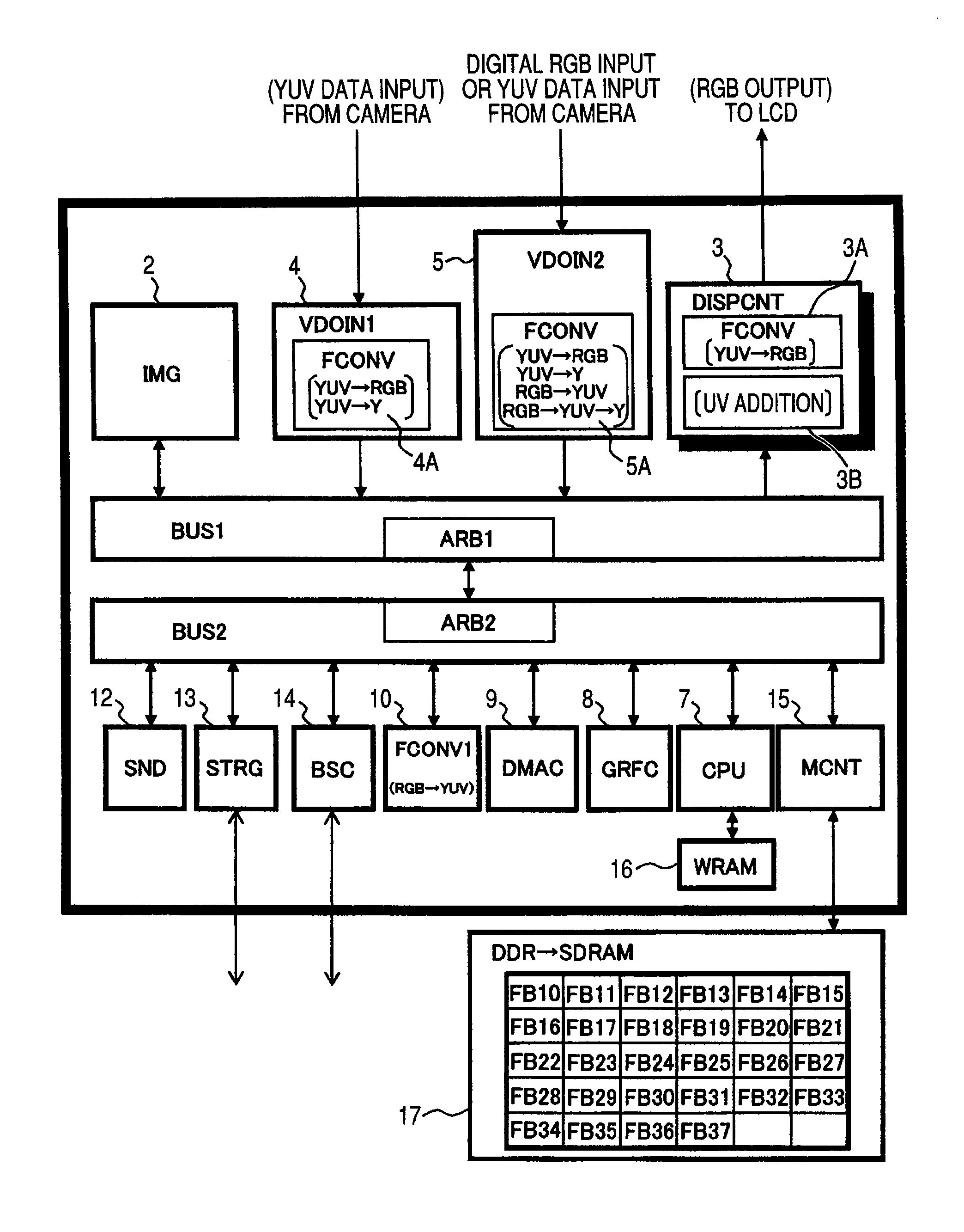
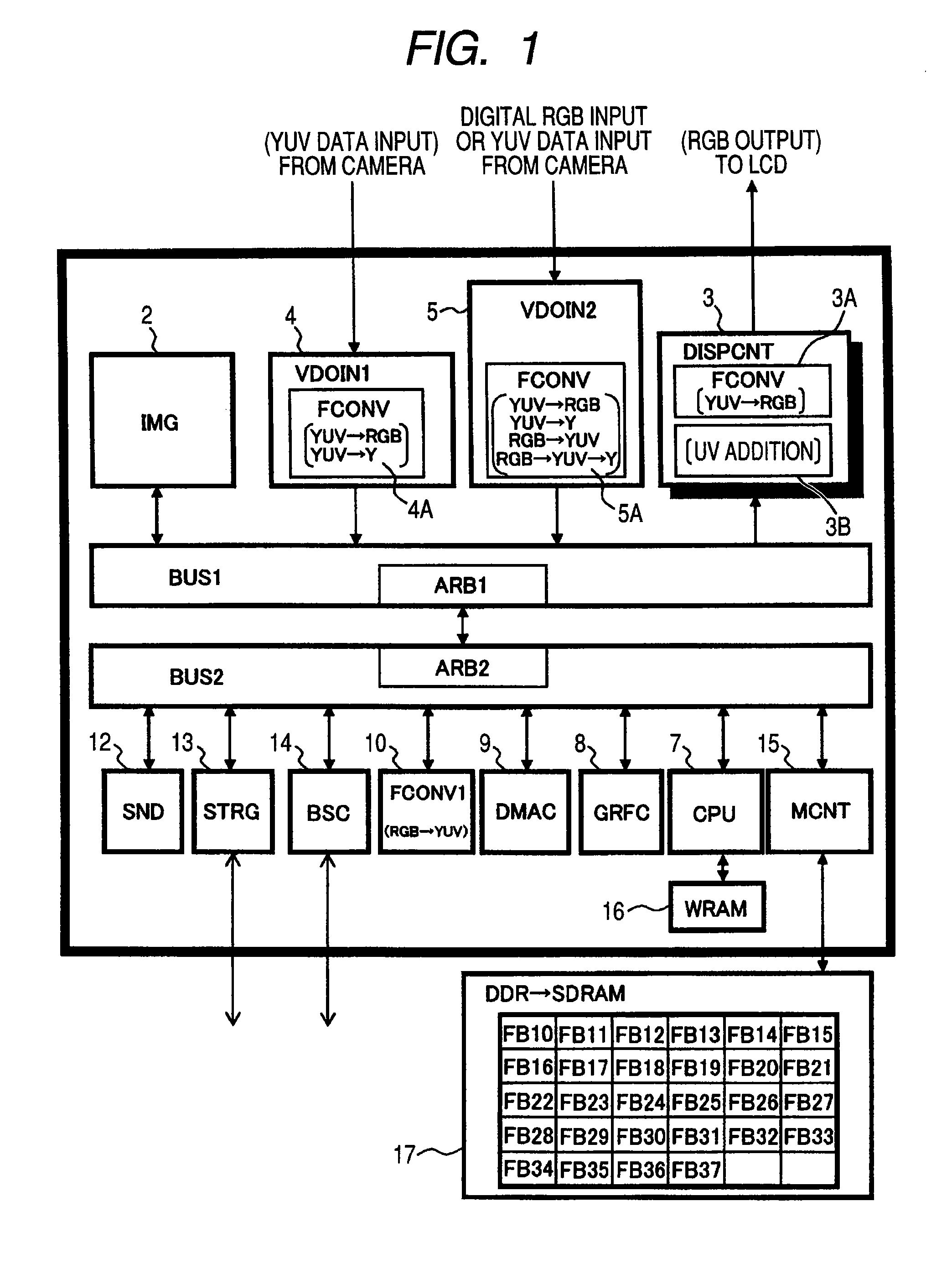
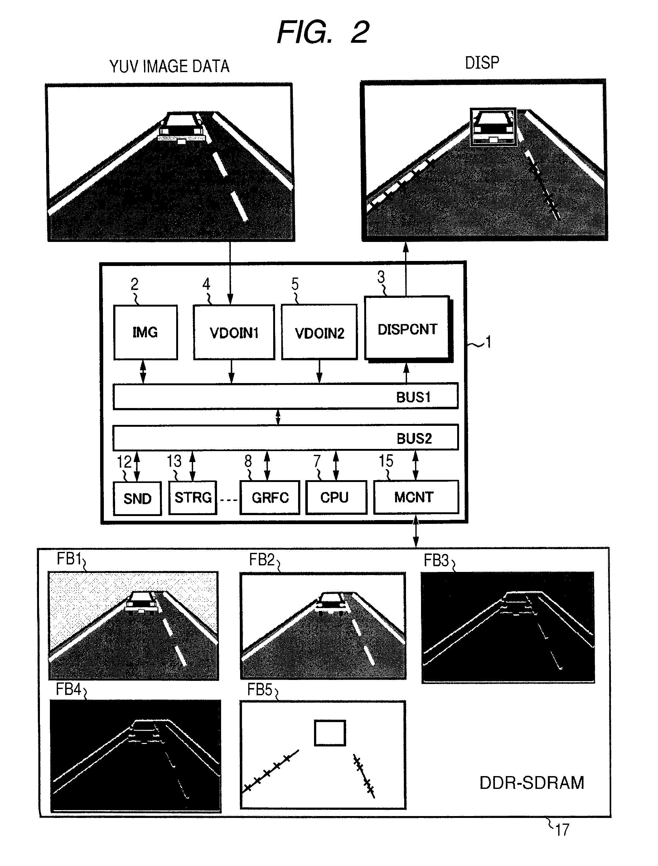
[0048]FIG. 1 shows an image data processor to which the invention is applied. An image data processor 1 shown in the diagram is formed by mounting various accelerators and the like for performing an image process on a single semiconductor substrate made of single crystal silicon or the like as an SOC (System On Chip) by, for example, a complementary MOS integrated circuit manufacturing technique. Although not limited, the image data processor 1 is applied to various image processes in an in-vehicle navigation system.

[0049]The image data processor 1 has, as internal buses, for example, a first bus BUS1 and a second bus BUS2. To the first bus BUS1, an image recognizing process accelerator (IMG: image recognizing module) 2 requested to have high data bandwidth and real-time performance, a display controller (DISPCNT) 3 particularly requested to have real-time performance, an image data input unit (VDOIN1) 4 and an image data input unit (VDOIN2) 5 are coupled as bus ...


PUM


Abstract

A data processor that includes a central processing unit, a graphic controller, a display controller, an image recognizing module, a memory controller and image data input units is disclosed. The components can be formed on a single semiconductor substrate. The display controller can perform display control on image data. The image data input unit stores the image data into a first area in the external memory. The image recognizing module or central processing unit executes an image process on the image data in the first area or image data in a second area, and stores a result of the process in a third area of the external memory.

Description

CROSS-REFERENCE TO RELATED APPLICATIONS[0001]The disclosure of Japanese Patent Application No. 2006-194146 filed on Jul. 14, 2006 including the specification, drawings and abstract is incorporated herein by reference in its entirety.BACKGROUND OF THE INVENTION[0002]The present invention relates to a data processor performing image recognition and display control on input image data and a technique effectively applied to, for example, an in-vehicle navigation system.[0003]As data processing systems for receiving image data in a real-time manner and performing image recognition such as feature extraction on input image data, image display control using the recognition result, and the like, there are an in-vehicle navigation system, a surveillance camera system, and the like. As a data processor applied to a navigation system, for example, Japanese Unexamined Patent Publication No. 2000-79860 describes a controller of a parking assistance system including an image recognizing apparatus...

Claims


Application Information

Patent Timeline
Patent Type & Authority Patents(United States)
IPC IPC(8): G06F13/14G06F13/18G06K9/46G06K9/40G09G5/39
CPCG06K9/00986G06T1/20G06V10/955G08G1/0968G06T7/00G06T2200/28
Inventor KURATA, SHUJISAITO, SEIICHIMATSUMOTO, YOSHIYUKI
Owner RENESAS ELECTRONICS CORP
Learn More