
Apparatus and method for winding a roving onto a bobbin

Active Publication Date: 2011-10-25
MASCHINENFABRIK RIETER AG
View PDF9 Cites 4 Cited by
  • Summary
  • Abstract
  • Description
  • Claims
  • Application Information

AI Technical Summary

Benefits of technology

[0017]The draftable roving has a specific strength which, on the one hand, allows later drafting in a drafting arrangement of a fine-spinning machine and, on the other hand, makes it possible to wind and unwind the roving and transport it to a drafting arrangement of a fine-spinning machine without wrong drafts. The strength is preferably achieved by means of a protective twist in the roving.
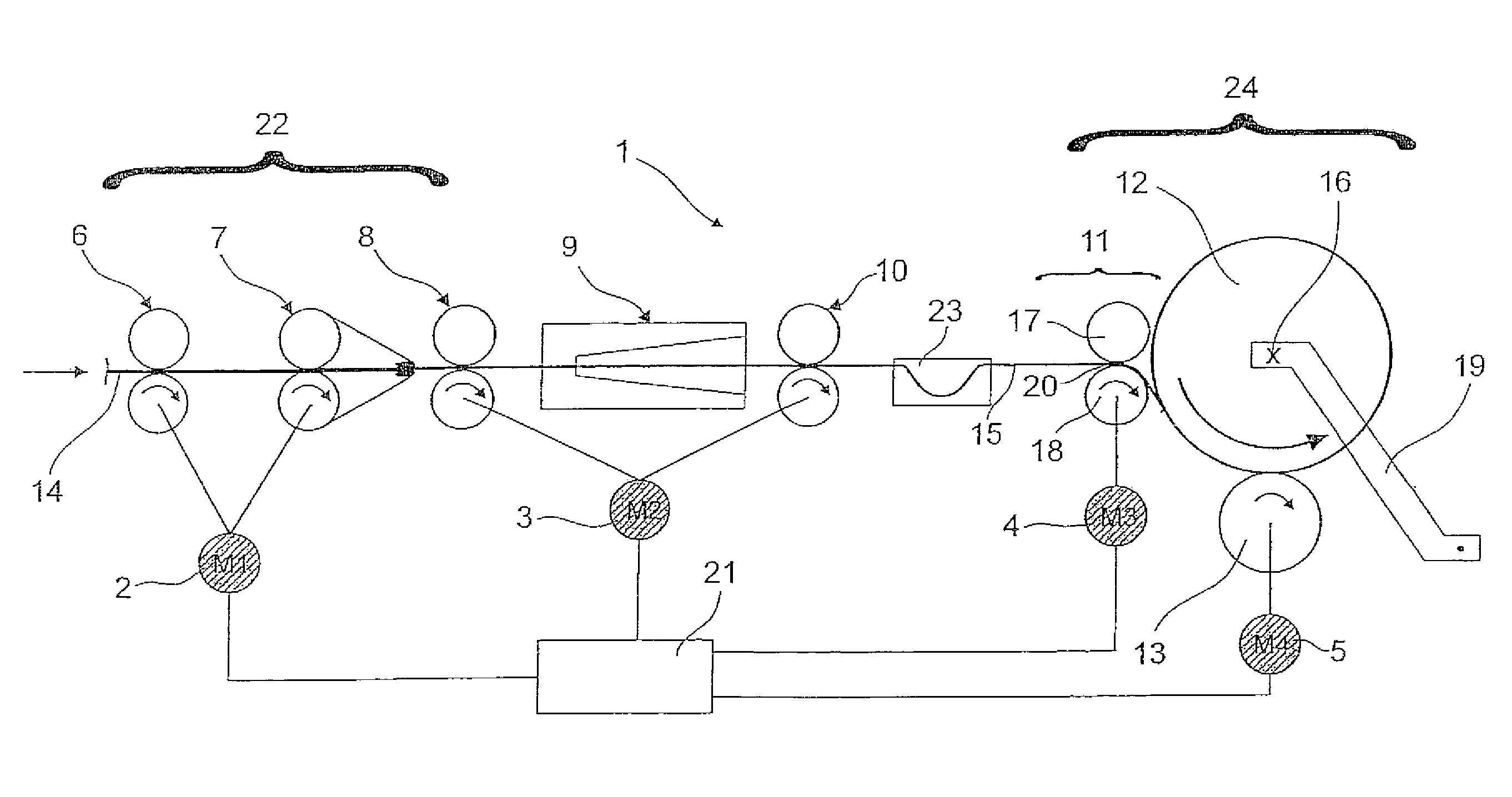
[0026]It is advantageous, however, if the roving length between the nip and the winding point is as small as possible. This is achieved, for example, in that, on the one hand, an attempt is made to bring the nip of the pair of winding delivery rollers as near as possible to the roving bobbin and, on the other hand, a partial looping of the roving on the tacho or drive roller and / or on the lower or upper roller of the pair of winding delivery rollers is provided.
[0041]It is also sufficient to regulate the rotational speed of the pair of winding delivery rollers by means of the primary control loop or by means of the bobbin rotational speed.
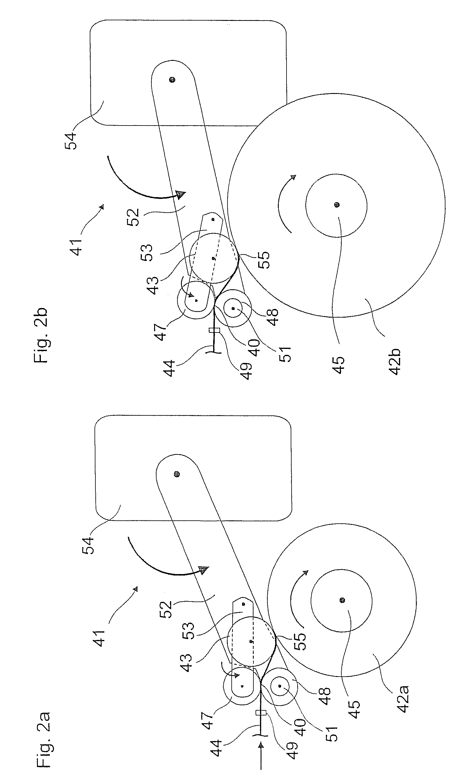
[0046]The, for example, spring-loaded jockey arm or jockey bar deflects the roving transversely to its running direction and at the same time keeps it under tension. Owing to the torque load on the jockey arm or jockey bar, the roving loop produced then automatically becomes larger if more roving than is wound is delivered. Conversely, the roving store is capable of also dispensing the roving again, as required. As a result, in spite of a different roving delivery or in spite of a change in roving tension, a constant roving tension is achieved, downstream of the nozzle outlet, upon entry into the pair of winding delivery rollers. Furthermore, the tension fluctuations caused during the traversing of the roving as a result of path changes in the run of the roving are also compensated.
[0047]It is advantageous, furthermore, if the roving tension upon entry is as low as possible, that is to say is near to zero or lower at least by a factor 2 to 10 than upon exit. Thus, the roving tension or its variability upon entry into the nip line is less important in the torque calculation and the regulation of the roving tension upon exit becomes more accurate.

Problems solved by technology

The flyer is, particularly because of the winding, a complicated and costly machine in the spinning process.
However, this low production cannot be increased with regard to the winding system using flyers, since a higher speed is limited by the centrifugal force which the flyers must withstand.
If, then, the roving is to be wound at high speed onto a roving tube, without wrong drafts or even roving breaks or later yarn breaks occurring, the take-over of conventional winding devices is unsuitable.
Particularly in the region of the traversing device, considerable problems arise when roving is being wound and may lead to wrong drafts or even roving breaks.

Method used


Image

  • Apparatus and method for winding a roving onto a bobbin
  • Apparatus and method for winding a roving onto a bobbin
  • Apparatus and method for winding a roving onto a bobbin

Examples


Embodiment Construction

[0059]Reference will now be made to embodiments of the invention, one or more examples of which are shown in the drawings. Each embodiment is provided by way of explanation of the invention, and not as a limitation of the invention. For example features illustrated or described as part of one embodiment can be combined with another embodiment to yield still another embodiment. It is intended that the present invention include these and other modifications and variations to the embodiments described herein.

[0060]FIG. 1 shows diagrammatically a spinning station 1 of a roving machine (the entire roving machine is not shown) according to the invention. This possible embodiment of the invention has a drafting arrangement 22 (likewise illustrated diagrammatically) which is supplied with a fibre composite 14 (for example, a doubled draw sliver). The drafting arrangement 22 is a double-apron drafting arrangement with a pair of entry rollers 6 and with a pair of main drafting rollers 7, betw...


PUM


Abstract

The invention relates to an apparatus for winding a roving provided with a protective twist onto a roving bobbin, containing a bobbin mounting for the rotatable mounting of a roving bobbin and a traversing device for traversing in the bobbin axial direction the roving to be wound. The traversing device comprises a driven pair of winding delivery rollers arranged directly in front of the roving bobbin and having a nip line through which the roving to be wound is guided.

Description

FIELD OF THE INVENTION[0001]The present invention relates to an apparatus for winding a draftable roving onto a bobbin, to an apparatus for producing a roving having a winding apparatus according to the invention, and to a method for producing a roving using a roving production apparatus according to the invention.[0002]A winding apparatus for winding a roving according to the invention contains a bobbin mounting for the rotatable mounting of a roving bobbin and a traversing device for traversing in the axial direction of the bobbin the roving to be wound, in order to obtain a package according to instructions.BACKGROUND[0003]Roving machines serve for producing a roving which is used as a model for spinning into a fibre yarn, for example on a ring-spinning machine, a drawer sliver being drafted in a drafting arrangement of the roving machine, and this fibre composite subsequently acquiring a twist before it is wound as fibre stubbing, with a protective twist, onto a feed bobbin.[000...

Claims


Application Information

Patent Timeline
IPC IPC(8): D01H13/04
CPCD01H1/36D01H1/40B65H51/10D01H7/92B65H54/36B65H59/384B65H54/28B65H2701/31
Inventor GRIESSHAMMER, CHRISTIANGEHRING, DAVIDLEHNER, FABIANMARTI, PASCAL
Owner MASCHINENFABRIK RIETER AG
Learn More