
Lightguide comprising a low refractive index region

a low refractive index, lightguide technology, applied in the direction of optical elements, lighting and heating apparatus, instruments, etc., can solve the problems of inefficient process, significant light loss, and okumura teachings that do not account for asymmetricalities, so as to improve the angular luminous intensity of the light emitting device

Inactive Publication Date: 2011-10-11
MASSACHUSETTS DEV FINANCE AGENCY +1
View PDF7 Cites 296 Cited by
  • Summary
  • Abstract
  • Description
  • Claims
  • Application Information

AI Technical Summary

Benefits of technology

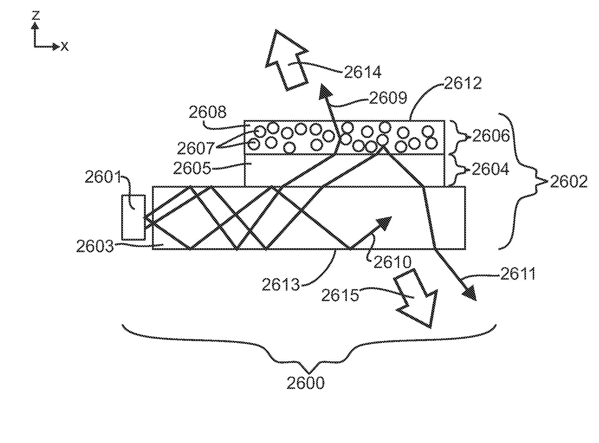
[0005]In one embodiment of this invention, a lightguide comprises a low refractive index region disposed between light extracting region and a non-scattering region. In further embodiment of this invention, volumetric scattering lightguide comprises a low refractive index region disposed between a volumetric scattering region and a non-scattering region. In some embodiments, a light emitting device comprising a volumetric scattering lightguide can angularly filter light input into the edge of a volumetric scattering lightguide by controlling the refractive index of the low refractive index region relative to the refractive index of the non-scattering region to prevent direct illumination of the volumetric scattering region, provide a luminance uniformity greater than 70%, or improve the angular luminous intensity of the light emitting device.

Problems solved by technology

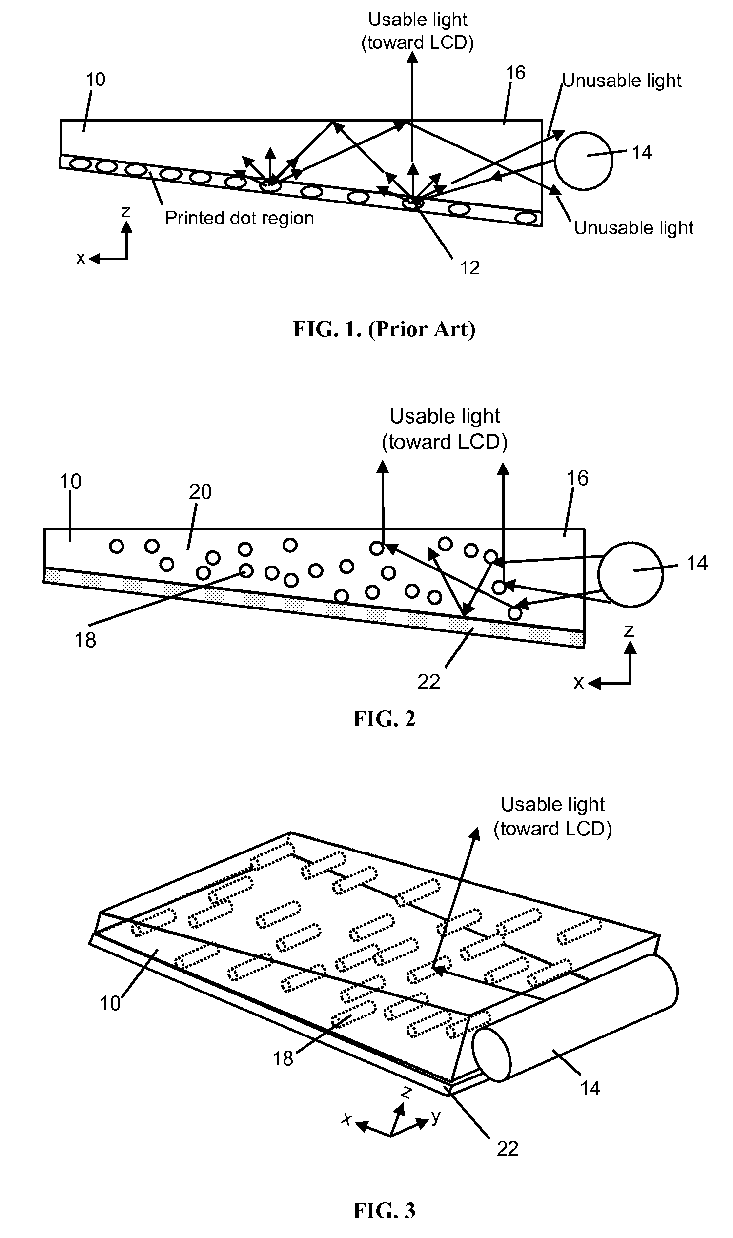
Thus, between the white dots spreading light out into larger angles than needed, and then using collimating films to bring a portion of this light back toward the normal or desired viewing angles, a significant amount of light is lost and the process is an inefficient one.
The Okumura teachings do not account for the asymmetric nature of the input light, or the need for more light to be diffused vertically, horizontally, or out from the main face of the light guide.
Also, traditional designs using planar lightguides such as used with LCDs have angular output, thermal, uniformity, efficiency, and form factor limitations.
Light from light sources such as LEDs that are incident upon a volumetrically scattering lightguide can have significantly bright regions near the LEDs due to light directly reaching the volumetric scattering region and causing bright luminance non-uniformities on the light emitting surface near the edge of the lightguide.

Method used


Image

  • Lightguide comprising a low refractive index region
  • Lightguide comprising a low refractive index region
  • Lightguide comprising a low refractive index region

Examples


example 1

[0420]A light emitting device, in accordance with the present invention, can be produced as described in FIG. 3, that is designed to have increased optical efficiency and therefore increased brightness relative to existing backlights. This is possible because the volumetric asymmetric diffusive region within the light guide allows for better control over the light scattering. Light from two CCFL lamps is coupled into the light guide. The light guide contains light scattering particles in a host matrix material. The particle chosen may be a polystyrene bead of diameter 5 μm dispersed at concentrations up to 10% by volume in a host matrix of acrylic. Other choices of particles and host matrix may provide equivalent performance. Asymmetry and alignment of the asymmetry can be created by stretching or extrusion processes. The asymmetrically diffusing light guide can be created by extruding, casting or coating, the mixture containing the particles. The light guide may be 2.5 mm in thickn...

example 2

[0421]A light emitting device, in accordance with the present invention, can be produced as described in FIG. 11, that is designed to have increased optical efficiency and therefore increased brightness relative to existing light emitting devices. This is possible because the volumetric asymmetric diffusive region below the light guide allows for better control over the light scattering. Two crossed asymmetric light scattering regions are optically coupled to the non-scattering light guide. Light from two CCFL lamps is coupled into the light guide. The asymmetric light scattering regions contain asymmetric particles in a host matrix material. The regions may be created by creating a mixture consisting of polystyrene bead particles of diameter 5 μm dispersed at concentrations up to 10% by volume in a host matrix of acrylic. Other choices of particles and host matrix may provide equivalent performance. The asymmetrically diffusing regions can be created by extruding, casting or coatin...

example 3

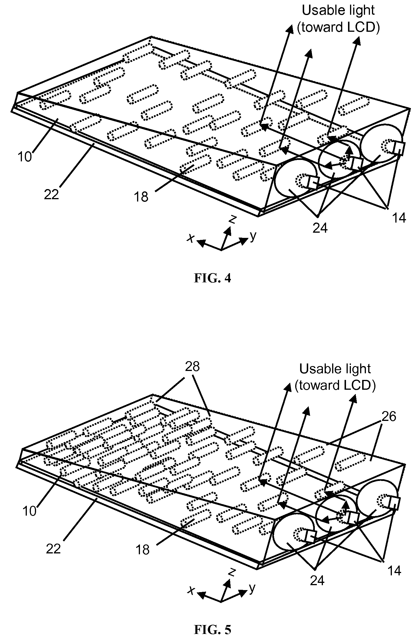
[0422]A light emitting device, in accordance with the present invention, can be produced as described in FIG. 8, that is designed to have increased optical efficiency and therefore increased brightness relative to existing backlights. This is possible because the volumetric asymmetric diffusive region within the light guide allows for better control over the light scattering. Light from more than one side-emitting RGB LEDs coupled into the light guide through holes in the light guide. The light guide contains asymmetric light scattering particles aligned parallel to the line of LEDs. The asymmetric light scattering light guide contain asymmetric particles in a host matrix material. The regions may be created by creating a mixture consisting of polystyrene bead particles of diameter 5 μm dispersed at concentrations up to 10% by volume in a host matrix of acrylic. Other choices of particles and host matrix may provide equivalent performance. The asymmetrically diffusing light guide ca...


PUM


Abstract

In one embodiment of this invention, a lightguide comprises a low refractive index region disposed between light extracting region and a non-scattering region. In further embodiment of this invention, volumetric scattering lightguide comprises a low refractive index region disposed between a volumetric scattering region and a non-scattering region. In some embodiments, a light emitting device comprising a volumetric scattering lightguide can angularly filter light input into the edge of a volumetric scattering lightguide by controlling the refractive index of the low refractive index region relative to the refractive index of the non-scattering region to prevent direct illumination of the volumetric scattering region, provide a luminance uniformity greater than 70%, or improve the angular luminous intensity of the light emitting device. The volumetric scattering lightguide may be curved, tapered, and a light emitting device comprising the same may further comprise at least one light source and a light redirecting element.

Description

RELATED APPLICATIONS[0001]This application is a continuation-in-part application of U.S. patent application Ser. No. 11 / 848,759, filed Aug. 31, 2007, now abandoned, and is a continuation of U.S. application Ser. No. 11 / 223,660, filed Sep. 9, 2005, now U.S. Pat. No. 7,278,775, which claims benefit of provisional application Ser. No. 60 / 608,233, filed Sep. 9, 2004, the disclosures of each are incorporated by reference in their entirety herein.FIELD OF THE INVENTION[0002]This invention generally relates to optical components and light emitting devices comprising optical components for illumination and methods of manufacturing the devices and components.BACKGROUND OF THE INVENTION[0003]Edge-illuminated lightguides have been used in backlights for LCDs and more recently for light fixtures. For extended color, longer lifetime, increased optical efficiency, and cost, LEDs are becoming utilized more in backlight assemblies instead of CCFLs. Since LEDs are closer to being a point source, LED...

Claims


Application Information

Patent Timeline
IPC IPC(8): F21V7/04F21V5/00
CPCG02B6/0036G02B6/0041G02B6/0043G02B6/0061G02F1/133606F21V2200/30G02B6/0046F21V7/04
Inventor KELLY, TIMOTHYCOLEMAN, ZANEYEO, TERENCE
Owner MASSACHUSETTS DEV FINANCE AGENCY
Learn More