
Programmable visible surface compositing

a visible surface and compositing technology, applied in the field of computer graphics, can solve the problems of many computationally expensive operations, transformation, and other computationally expensive operations of animation software tools, and the computer model of a character is often extremely complex, and achieve the effect of reducing the cost of operations, and increasing the cost of operations

Inactive Publication Date: 2011-09-27
PIXAR ANIMATION
View PDF7 Cites 5 Cited by
  • Summary
  • Abstract
  • Description
  • Claims
  • Application Information

AI Technical Summary

Benefits of technology

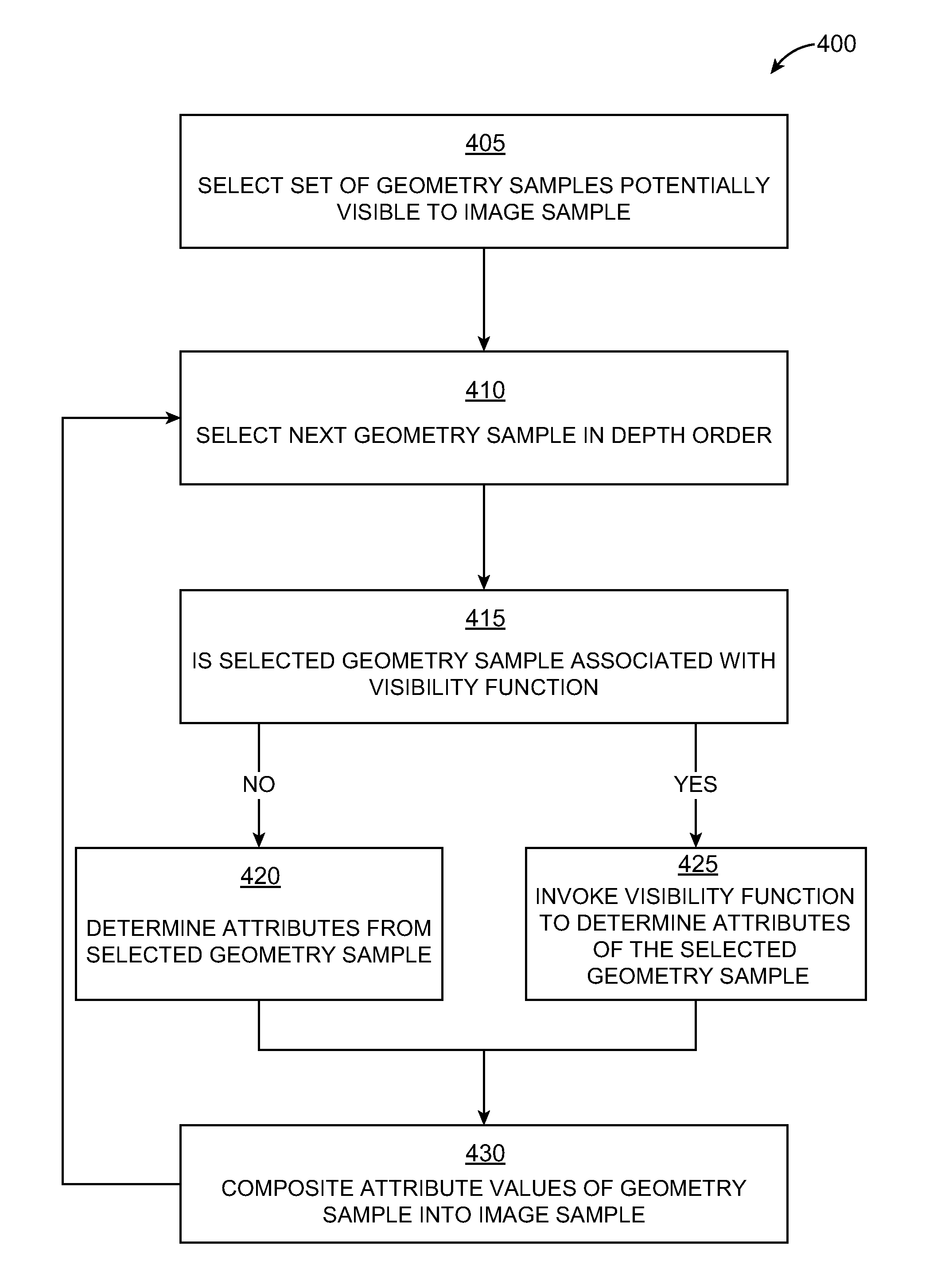
[0018]Additionally, an embodiment of the invention enables programmable or user-defined visibility functions. In an embodiment, a renderer traverses the set of geometry samples associated with an image sample. Rather than accumulate opacity and color in strict depth order, the renderer can invoke visibility functions associated with some or all of the geometry samples. Each geometry sample's visibility function can access attributes of any other geometry sample associated with the image sample. Furthermore, each geometry sample's visibility function can identify the position of its associated geometry sample and any other geometry samples in the depth sequence of geometry samples associated with an image sample. A visibility function can return any arbitrary value based on attributes of its associated geometry sample, attributes of other geometry samples associated with the image sample, and / or the position of geometry samples in the depth sequence associated with the image sample.

Problems solved by technology

To appear realistic, the computer model of a character is often extremely complex, having millions of surfaces and tens of thousands of attributes.
Due to the complexity involved with animating such complex models, animation tools often rely on animation variables to define the character's animation.
Animation software tools often need to perform many complex projections, transformation, and other computationally expensive operations on hundreds or thousands of particles, points, or other portions of model geometry to convert animation variable values into posed models.
This makes these types of operations computationally expensive to perform.
However, deformations of geometry can introduce small errors may cause the portions of the model geometry to inadvertently pass behind the guide surface or other objects.
Furthermore, many special illumination and rendering effects, such as motion blur and shadowing, may interact in visually undesirable ways.

Method used


Image

  • Programmable visible surface compositing
  • Programmable visible surface compositing
  • Programmable visible surface compositing

Examples


Embodiment Construction

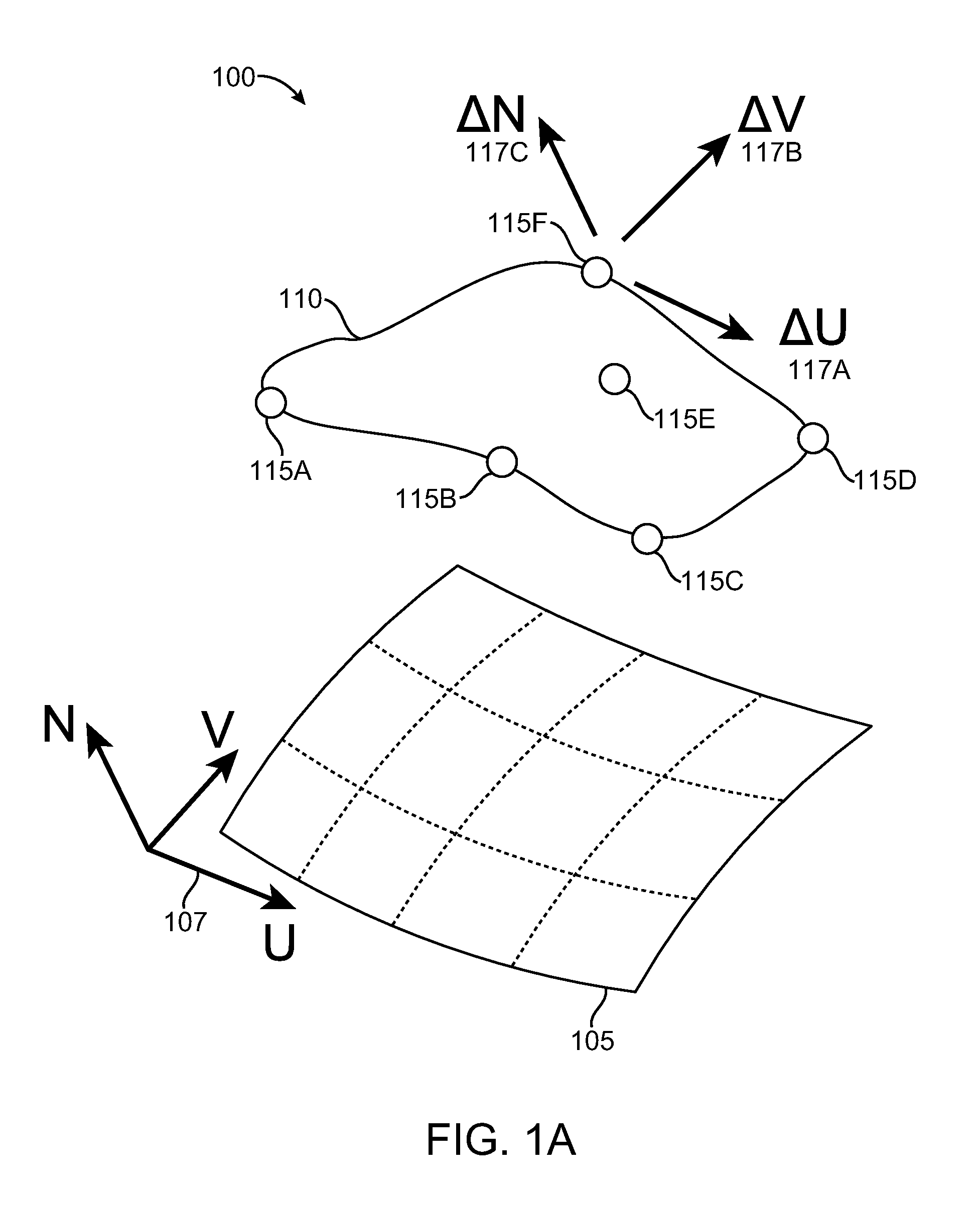
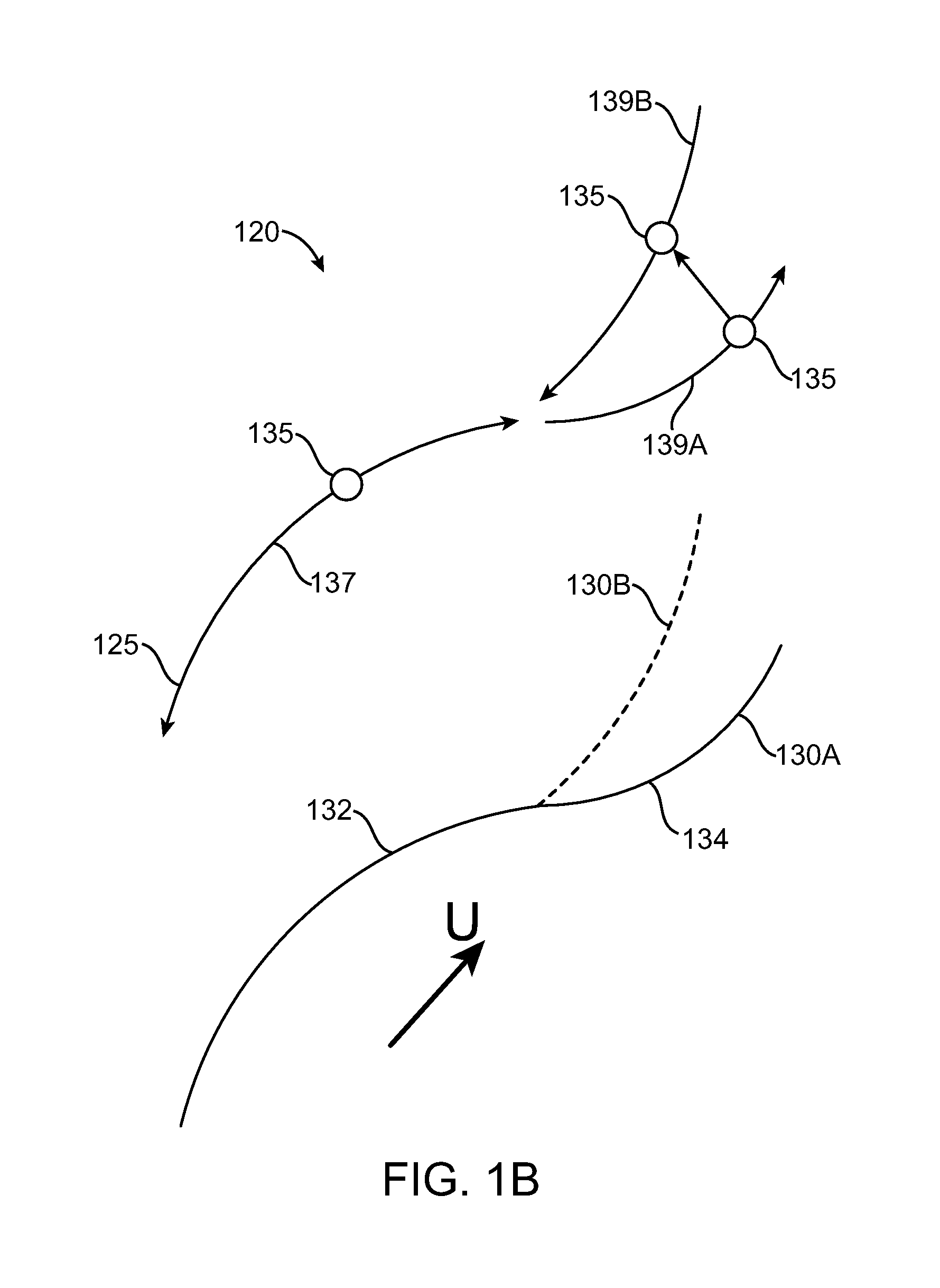
[0019]FIGS. 1A-1C illustrate example applications of an embodiment of the invention. FIG. 1A illustrates an example movement 100 of geometry with respect to a guide surface. This movement may be referred to as a surface pulling operation. A guide surface 105 may be any type of surface with a local coordinate system. The guide surface 105 may or may not be part of an object. The guide surface 105 may optionally be set to be rendered in a scene, or may be set to be invisible to the renderer. Examples of guide surfaces include flat surfaces or polygon meshes; curved surfaces, such as quadratic, cubic, Bezier surfaces or non-uniform rational B-splines (NURBS), subdivision surfaces, or any other higher order surfaces; as well as any other type of surface defined parametrically. The guide surface 105 is associated with a local coordinate system (u,v,n) 107, which defines vectors u and v tangent to the guide surface 105 at any point and a vector n normal to the guide surface at any point. ...


PUM


Abstract

Programmable or user-defined visibility functions can be defined to achieve rendering effects and eliminate rendering errors. A renderer traverses the set of geometry samples potentially visible to an image sample. Rather than accumulate opacity and color in strict depth order, the renderer can invoke visibility functions associated with some or all of the geometry samples. Each geometry sample's visibility function can access attributes of any other geometry sample associated with the image sample. Furthermore, each geometry sample's visibility function can identify the position of its associated geometry sample and any other geometry samples in the depth sequence of geometry samples associated with an image sample. A visibility function can return any arbitrary value based on attributes of its associated geometry sample, attributes of other geometry samples associated with the image sample, and / or the position of geometry samples in the depth sequence associated with the image sample.

Description

CROSS-REFERENCE TO RELATED APPLICATIONS[0001]This application claims priority to U.S. Provisional Patent Application No. 60 / 812,293, entitled “Sliding Patch Deformer and Programmable Visible Surface Compositing,” and filed Jun. 9, 2006, which is incorporated by reference herein for all purposes. This application is related to U.S. patent application Ser. No. 11 / 760,640, filed Jun. 8, 2007, and entitled “Sliding Patch Deformer,” which is incorporated by reference herein for all purposes.BACKGROUND OF THE INVENTION[0002]The present invention relates to the field of computer graphics, and in particular to methods and apparatus for creating, modifying the attributes and appearance of objects in computer graphics images. Many computer graphic images are created by mathematically modeling the interaction of light with a three dimensional scene from a given viewpoint. This process, called rendering, generates a two-dimensional image of the scene from the given viewpoint, and is analogous t...

Claims


Application Information

Patent Timeline
Patent Type & Authority Patents(United States)
IPC IPC(8): G06T15/40
CPCG06T15/00G06T17/30
Inventor LAUR, DAVIDMILLIRON, TIMOTHY S.PLANCK, MAXWELL
Owner PIXAR ANIMATION
Learn More