Gas discharge lamp ignition

a gas discharge and lamp technology, applied in the direction of gaseous cathodes, energy-saving lighting, sustainable buildings, etc., can solve the problems of requiring quite a bit of hardware to provide the starter circuit, the discharge of between the inner electrodes, and the termination of the supply of high-voltage pulses to the outer electrodes of the lamp, etc., to achieve the effect of simplifying the ignition of the gas discharged lamp, dissipating a significant amount of energy, and reducing the cost a gas discharge lamp ignition of a gas discharge lamp technology of gas discharge lamp and gas discharge gas discharge lamp and gas discharge gas discharge lamp technology, applied in the field of gas discharge lamp and ignition of gas discharge lamp gas discharge and ignition of gas discharge and ignition of gas discharge and ignition of gas discharge which is applied in the field of gas discharge and ignition of gas discharge and other problems, achieve the effect of gas discharge and the resonance circui

Inactive Publication Date: 2011-09-20
KONINKLIJKE PHILIPS ELECTRONICS NV
View PDF13 Cites 2 Cited by
  • Summary
  • Abstract
  • Description
  • Claims
  • Application Information

AI Technical Summary

Benefits of technology

[0006]By doing so ignition of a gas discharged lamp is simplified. The resonance circuit will stop working automatically upon discharging of the gas between the inner electrodes of the lamp. Therefore, after ignition, the resonance circuit will not consume and dissipate a significant amount of energy. As a consequence, only a fraction of a second for the ignition is to be taken into account for determining the dimensions of parts of the resonance circuit to handle said energy. As a result, the resonance circuit can be made small and cheap and it can be arranged close to the lamp, possibly to form an integral lighting unit together with the lamp. Only two conductors are required to ignite and to supply such lighting unit. Using a coaxial cable between the supply device and the lighting unit provides a relatively simple and cheap connection means, which provides excellent shielding against electromagnetic interference (EMI) in addition.
[0007]U.S. Pat. No. 6,563,267, mentioned above, discloses the use of an external electrode or antenna, which is arranged at the outside of a seal across the cavity of said seal. The external electrode is connected to the electrode extending through the other seal only. The external electrode reduces a possible ignition delay upon re-ignition of the lamp directly after it has been extinguished, which effect is referred to as hot restrike.

Problems solved by technology

This may cause a discharge of between the inner electrodes, that is to ignition of the lamp.
As a result the electronic switch of the starter drive part will fail to conduct anymore, so that the supply of high voltage pulses to the outer electrode of the lamp terminates.
A disadvantage of said prior art is that it requires quite some hardware to provide the starter circuit, such as a high voltage transformer and an electronic switch.
Another disadvantage of said prior art is that it requires three conductors to connect the feed circuit part to the lamp unit, of which one conductor is used during less of a second for igniting the lamp only.
As a result a dedicated, expensive cable is required to connect the feed circuit part to the lamp unit.
A further disadvantage of the prior art is that a supply voltage for the lamp having a high frequency, for example above 2 MHz will be too expensive to be used in many cases.

Method used


Image

  • Gas discharge lamp ignition
  • Gas discharge lamp ignition

Examples


first embodiment

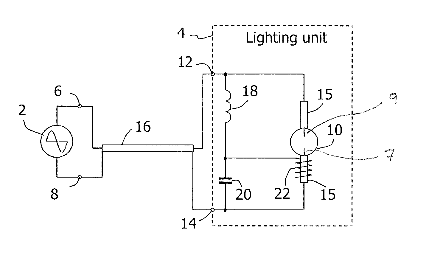
[0011]The diagram of FIG. 1 shows a lighting system in which the invention is applied. The system comprises, as main components, a supply device 2 and a lighting unit 4. The supply device 2 supplies an alternating voltage to its terminals 6, 8. The lighting unit 4 comprises a gas discharge lamp 10, which has a space or vessel, which contains a gas, first inner electrode 7 and second inner electrode 9, which are connected to terminals 12 and 14 of the lighting unit 4.

[0012]On opposite sides the lamp 10 it may have an elongated seal portion 15 which has a cavity containing a gaseous constituent, such as mercury vapor. A foil of, for example, molybdenum, extends along the length of the cavity. An arrangement comprising such seal 15 is called an UV enhancer. The use of an UV enhancer is disclosed by U.S. Pat. No. 6,563,267. An UV enhancer constitutes a start-promoting means as a source of UV radiation when applying an electric voltage across the cavities.

[0013]It must be noted that the ...

second embodiment

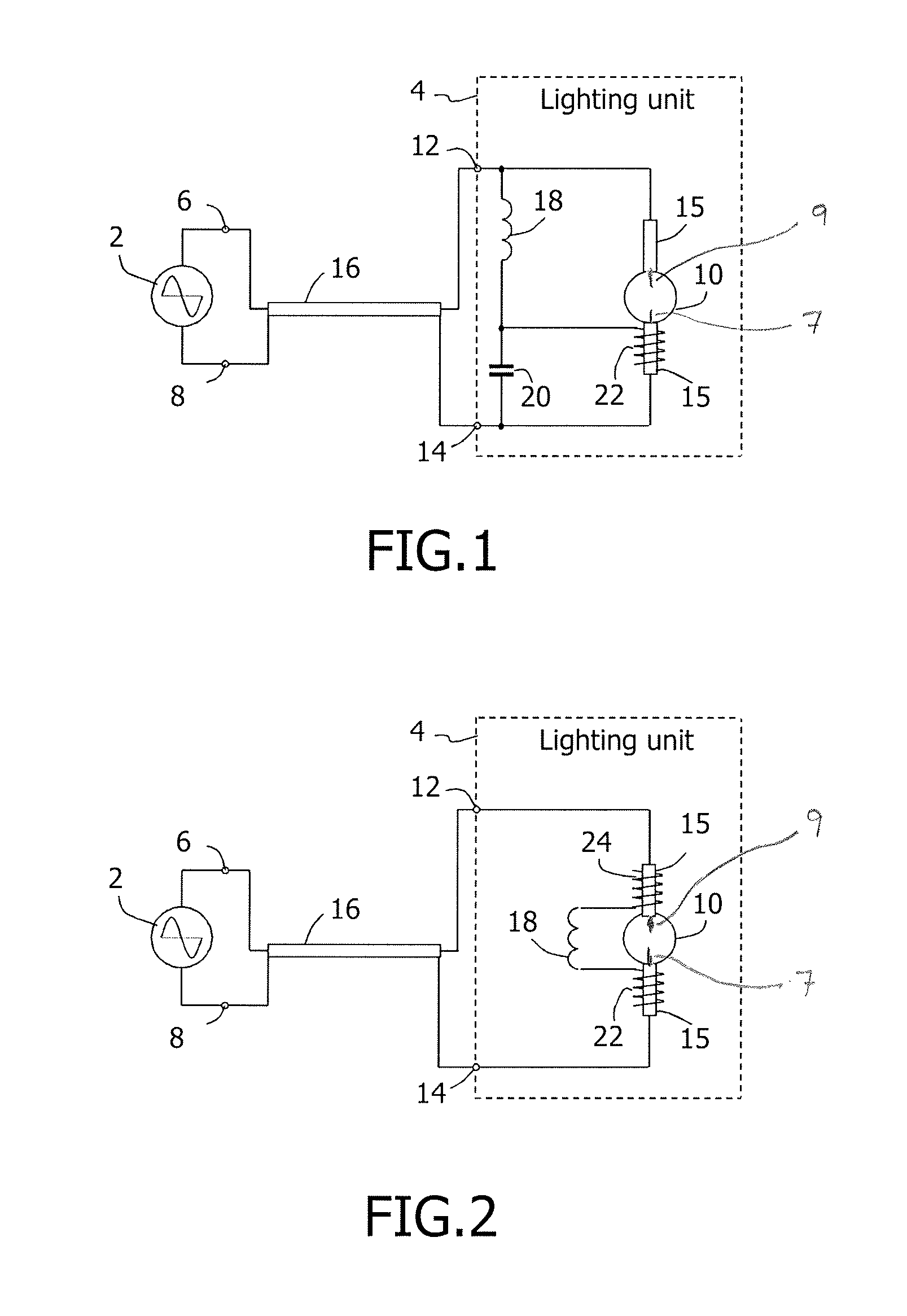
[0023]FIG. 2 shows a diagram of a lighting system in which the invention is applied. The diagram differs from that shown in FIG. 1 by (I) no external capacitor is used, the resonance is designed with the intrinsic capacity between antenna 22 and lamp connections / electrodes, (II) the connection of inductance 18 to terminal 12 is replaced by another capacitor comprised of a second outer electrode 24, which is arranged nearer to the second inner electrode 9 than the first inner electrode 7 near the first electrode 22 of FIG. 1. Just like the first outer electrode 22, the second outer electrode provides a capacity together with its near inner electrode. By connecting the inductor 18 between the two outer electrodes a similar effect during start up of the system as with the system of FIG. 1 is obtained. High electric fields (voltage) are provided on both sides of the lamp. The arrangement of FIG. 2 with two outer electrodes may be more cost effective. Depending on requirements given from...


PUM


Abstract

Ignition of a gas discharge lamp 10, which has a gas containing main space and two inner electrodes, of a lighting unit 4 of a lighting system is achieved by the use of a high frequency resonance circuit. The resonance circuit is connected to the inner electrodes and to a supply device 2, which supplies an alternating supply voltage. An outer electrode 22 is arranged near one the inner electrodes and to a node of the resonance circuit. Upon supplying the supply voltage a high voltage alternating burst will be generated at the outer electrode. This will result into a discharge of the gas in the main space. In turn, this will induce a discharge of the remaining gas. Then the frequency of the supply voltage will increase and a small reactive current only will remain to flow through the resonance circuit.

Description

FIELD OF THE INVENTION[0001]The invention relates to igniting a gas discharge.BACKGROUND OF THE INVENTION[0002]U.S. Pat. No. 6,734,643 discloses a lighting system comprising a feed circuit part, a lamp unit which contains a gas discharge lamp and a starter circuit. The starter circuit is divided in a starter drive part, which is contained in the feed circuit part, and a high voltage generating part, which is contained in the lamp unit. The feed circuit part further comprises a feed circuit for supplying an alternating supply voltage to the lamp unit, and a starter drive part. The lamp unit comprises a lamp and a high voltage generating part. Inner electrodes of the lamp are connected via two terminals of the lamp unit and via two terminals of the feed circuit part to the supply source. An outer auxiliary electrode of the lamp and an inner electrode of the lamp are connected to the high voltage generating part of the lamp unit. The high voltage generating part is connected via two te...

Claims


Application Information

Patent Timeline
Patent Type & Authority Patents(United States)
IPC IPC(8): H05B41/00
CPCH05B41/042H05B41/2881Y02B20/204Y02B20/00
Inventor DEPPE, CARSTENLUERKENS, PETERDURAN, RAUL
Owner KONINKLIJKE PHILIPS ELECTRONICS NV
Why Eureka
Try Eureka