
Patterned perpendicular magnetic recording medium with exchange coupled recording layer structure and magnetic recording system using the medium

a technology of magnetic recording medium and exchange coupled recording layer, which is applied in the direction of data recording, instruments, coating parts of support with magnetic layers, etc., can solve the problems of limiting the achievable density of patterned perpendicular media, and affecting the accuracy of the magnetic recording. , to achieve the effect of favorable field angle dependence and robust on-track write process

Inactive Publication Date: 2011-09-20
WESTERN DIGITAL TECH INC
View PDF20 Cites 5 Cited by
  • Summary
  • Abstract
  • Description
  • Claims
  • Application Information

AI Technical Summary

Benefits of technology

The solution results in a narrower switching field distribution, enabling a more robust on-track write process and improved field angle dependence, reducing the likelihood of adjacent track overwrite and enhancing data density and recording performance.

Problems solved by technology

One problem associated with patterned perpendicular media is the relatively wide variation in the coercive field among the individual magnetic islands, sometimes also called “dots”.
Additionally, it has been found that the SFD broadens (that is, the bit-to-bit variation in the coercive field increases) as the size of the magnetic islands is reduced, which limits the achievable density of patterned perpendicular media.
An additional problem arises in patterned perpendicular media because of a key difference with conventional continuous perpendicular media, namely the fact that in conventional continuous media the linear density (along-the-track density of the bits) is typically 4 to 6 times the track density (the density of the tracks in the radial or cross-track direction), while in patterned media the linear density and track density will be about the same.
Thus, much higher track densities are anticipated for patterned media which will result in greater adjacent track interference during reading and overwriting of adjacent tracks during writing.
This may result in fringing fields from the write head leaking into dots in adjacent tracks which can cause inadvertent overwriting.
This problem is exacerbated because the fringing fields acting on dots in adjacent tracks encompass relatively large angles with the perpendicular easy-axis of the recording layer on the dots, which increases the likelihood of adjacent track overwrite.

Method used


Image

  • Patterned perpendicular magnetic recording medium with exchange coupled recording layer structure and magnetic recording system using the medium
  • Patterned perpendicular magnetic recording medium with exchange coupled recording layer structure and magnetic recording system using the medium
  • Patterned perpendicular magnetic recording medium with exchange coupled recording layer structure and magnetic recording system using the medium

Examples


Embodiment Construction

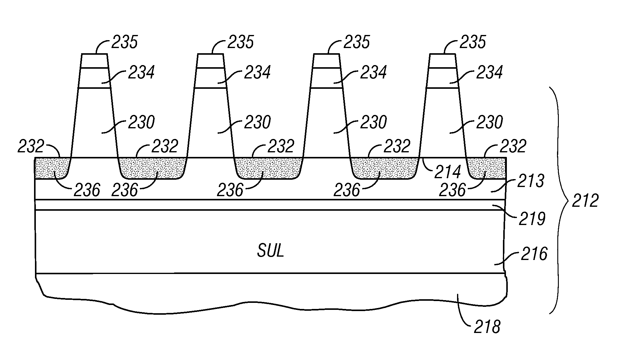
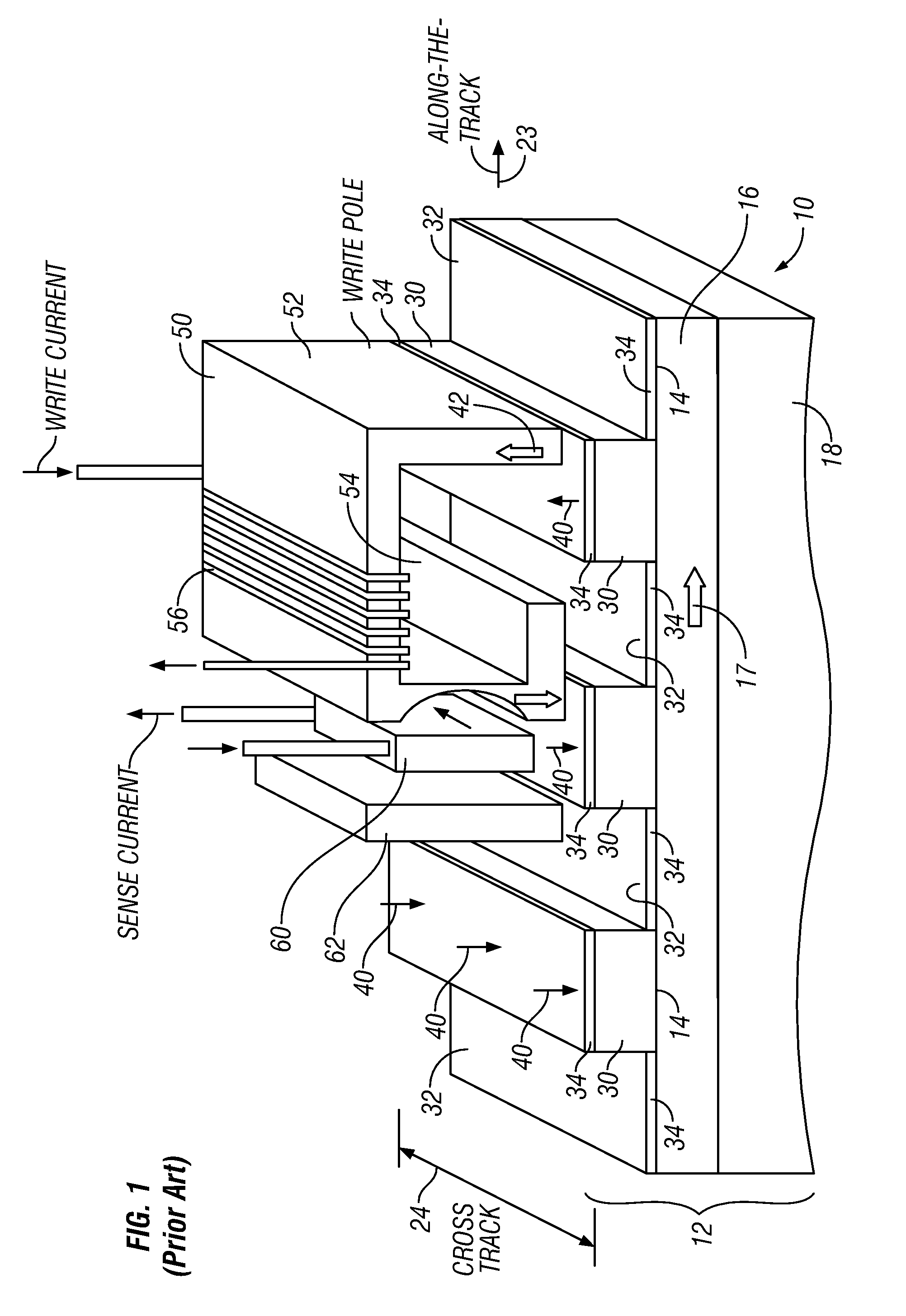
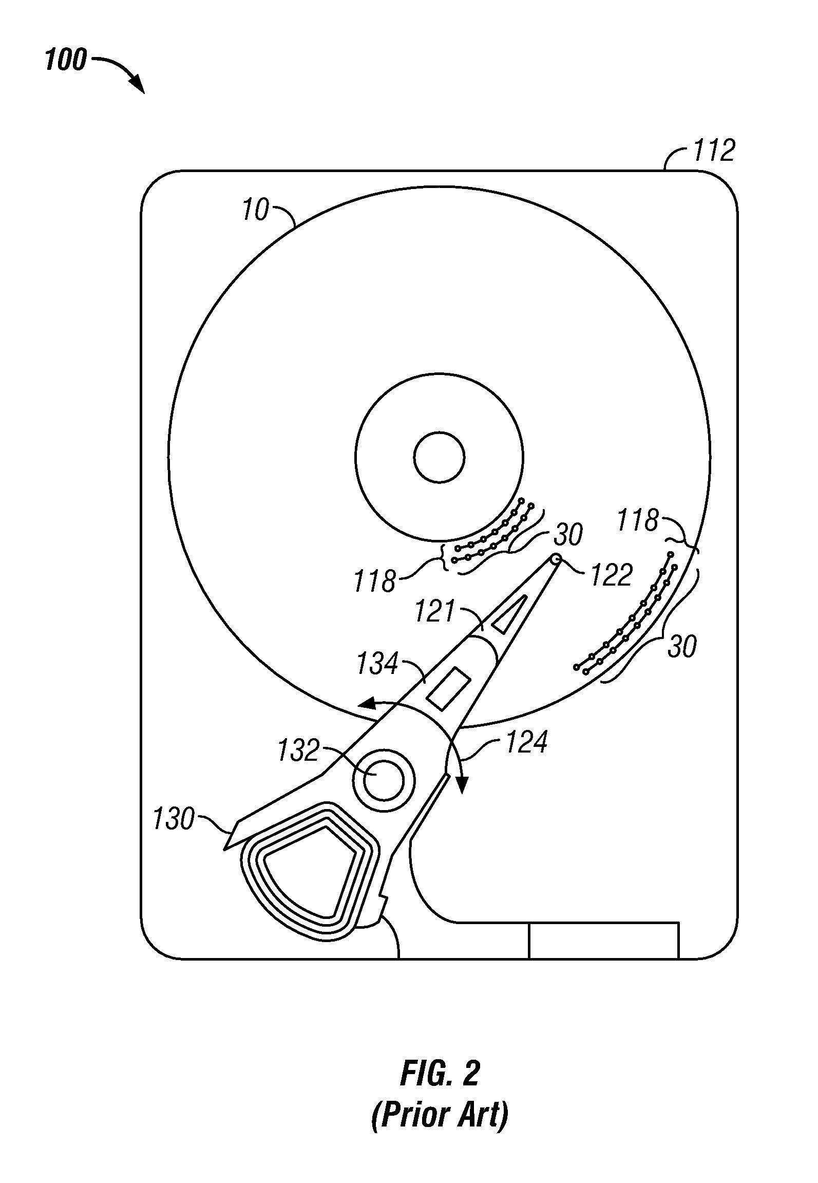
[0028]FIG. 1 is a schematic representation of a prior art perpendicular magnetic recording system with patterned perpendicular media. The system can be implemented in a magnetic recording disk drive, with the medium being a magnetic recording disk with the patterned bits arranged into concentric circular data tracks. FIG. 1 thus shows a portion of a disk 10 that includes a substrate 12 with a generally planar surface 14. A plurality of discrete patterned islands or pillars 30 extend generally perpendicularly from the surface 14 and are part of substrate 12. The pillars 30 are spaced apart, leaving troughs or trenches 32 recessed below the ends of the pillars 30. A layer 34 of perpendicular magnetic recording material is formed on the ends of the pillars 30 as well as on surface 14 in the trenches 32. The recording layer 34 on each of the pillars 30 is magnetized perpendicularly, as depicted by arrows 40, resulting in the recorded bits being stored in the recording layer 34 in a gene...


PUM

PropertyMeasurementUnit
widthaaaaaaaaaa
widthaaaaaaaaaa
widthaaaaaaaaaa

Abstract

A patterned perpendicular magnetic recording medium has discrete magnetic islands, each of which has a recording layer (RL) structure that comprises two exchange-coupled ferromagnetic layers. The RL structure may be an “exchange-spring” RL structure with an upper ferromagnetic layer (MAG2), sometimes called the exchange-spring layer (ESL), ferromagnetically coupled to a lower ferromagnetic layer (MAG1), sometimes called the media layer (ML). The RL structure may also include a coupling layer (CL) between MAG1 and MAG2 that permits ferromagnetic coupling. The interlayer exchange coupling between MAG1 and MAG2 may be optimized, in part, by adjusting the materials and thickness of the CL. The RL structure may also include a ferromagnetic lateral coupling layer (LCL) that is in contact with at least one of MAG1 and MAG2 for mediating intergranular exchange coupling in the ferromagnetic layer or layers with which it is in contact (MAG2 or MAG1). The ferromagnetic alloy in the LCL has significantly greater intergranular exchange coupling than the ferromagnetic alloy with which it is in contact (MAG2 or MAG1).

Description

BACKGROUND OF THE INVENTION[0001]1. Field of the Invention[0002]This invention relates generally to patterned perpendicular magnetic recording media, such as disks for use in magnetic recording hard disk drives, and more particularly to patterned disks with data islands having improved magnetic recording properties.[0003]2. Description of the Related Art[0004]Magnetic recording hard disk drives with patterned magnetic recording media have been proposed to increase data density. In conventional continuous magnetic recording media, the magnetic recording layer is a continuous layer over the entire surface of the disk. In patterned media the magnetic recording layer on the disk is patterned into small isolated data islands arranged in concentric data tracks. Patterned-media disks may be longitudinal magnetic recording disks, wherein the magnetization directions are parallel to or in the plane of the recording layer, or perpendicular magnetic recording disks, wherein the magnetization d...

Claims


Application Information

Patent Timeline
Patent Type & Authority Patents(United States)
IPC IPC(8): G11B5/66
CPCG11B5/65G11B5/66G11B5/855G11B5/672
Inventor BERGER, ANDREAS KLAUSFULLERTON, ERIC E.HELLWIG, OLAVLENGSFIELD, III, BYRON HASSBERGMARINERO, ERNESTO E.
Owner WESTERN DIGITAL TECH INC
Learn More