Method, device and computer program of length measurement
a technology of measurement method and measurement method, applied in material analysis using wave/particle radiation, instruments, nuclear engineering, etc., can solve problems such as insatisfactory measurement of currently existing complex multi-layered circuit elements, prior technique approach fails to take into account, and applicability suffers
- Summary
- Abstract
- Description
- Claims
- Application Information
AI Technical Summary
Benefits of technology
Problems solved by technology
Method used
Image
Examples
embodiment 1
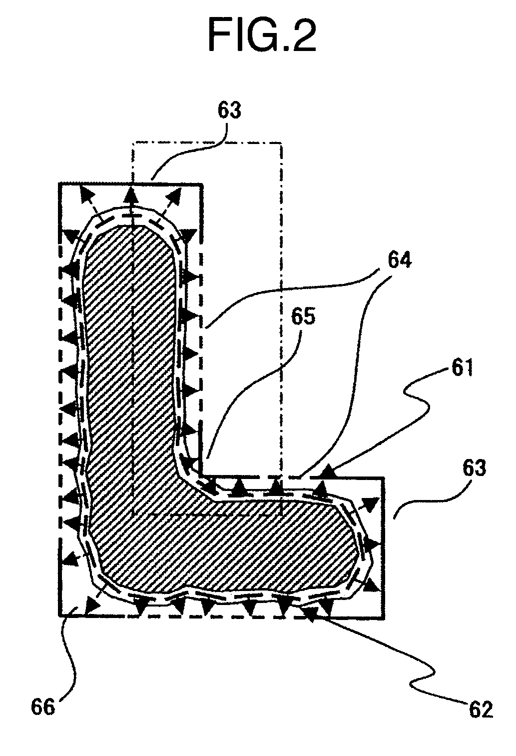
[0054]An example for measurement of the distance between an edge portion of scanning electron microscope (called SEM edge hereinafter) and design data will be explained with reference to some of the accompanying drawings below. This example will be referred to as Edge Placement Error (EPE) measurement in some cases.
[0055]FIG. 2 is a diagram showing a state in which the design data and a SEM image are laid over each other. While EPE measurement is the one that measures the distance between design data and SEM edge, it is often the case that the real semiconductor circuit element is formed so that a rectangular corner of pattern is deformed and corrupted into a rounded shape, for example. Upon execution of EPE measurement for such corner-rounded pattern, it is sometimes difficult to judge the exact direction along which the measurement is to be done.
[0056]In this example, in view of such problem, it is proposed to determine the length measurement direction when performing EPE measurem...
embodiment 2
[0088]An explanation will be given of an example which determines sampling points based on a length measurement result between design data and a Scanning Electron Microscope (SEM) edge, with reference to some of the accompanying drawings below. As shown in FIG. 2, when performing Edge Placement Error (EPE) measurement of a single pattern, a great number of candidates for the length measurement reference position are considered. However, the evaluation of a pattern from among all the measurement reference position candidates consumes much time and requires troublesome manual operations—this is not preferable in a viewpoint of measurement efficiency. On the other hand, it is very difficult to predetermine how a pattern will change from its ideal shape (design data): there is no guarantee that a measurement reference position as set up by a recipe is always the adequate length measurement location.
[0089]In this example, in view of the above-noted problem, it is proposed to perform leng...
embodiment 3
[0093]An example which categorizes length measurement results based on the state of design data concerning length measurement positions thereof will be explained with reference to some of the drawings below. FIG. 8 shows an example with a plurality of patterns being formed into a multilayered structure and is a drawing showing a display example wherein design data 82, 83 of an under layer and target layer are laid over a SEM image of a pattern having a poly-gate (target layer) 81 that is multilayered above an active area (under layer) 80.
[0094]When performing EPE measurement for a composite pattern making up a semiconductor circuit element, a very large number of measurement reference position candidates exist. However, it is not preferable in the viewpoint of measurement efficiency to evaluate the pattern based on length measurement results of all such measurement reference position candidates consumes much time and labors.
[0095]Below is an explanation about an example which relies...
PUM
 Abstract
Description
Claims
Application Information
 - R&D
- Intellectual Property
- Life Sciences
- Materials
- Tech Scout
- Unparalleled Data Quality
- Higher Quality Content
- 60% Fewer Hallucinations
Browse by: Latest US Patents, China's latest patents, Technical Efficacy Thesaurus, Application Domain, Technology Topic, Popular Technical Reports.
© 2025 PatSnap. All rights reserved.Legal|Privacy policy|Modern Slavery Act Transparency Statement|Sitemap|About US| Contact US: help@patsnap.com


