
Method and apparatus for achieving inherent ignition voltage in operation of a high intensity discharge lamp

Inactive Publication Date: 2011-09-13
2197611 ONTARIO
View PDF3 Cites 4 Cited by
  • Summary
  • Abstract
  • Description
  • Claims
  • Application Information

AI Technical Summary

Benefits of technology

[0015]In another embodiment, decreasing the ignition voltage is achieved by decreasing the frequency of the sweep frequency generator as applied to the resonant ignition network.
[0019]In yet another embodiment, the resonant ignition network is further operable to decrease the ignition voltage level to a decreased voltage level appropriate for steady state operation of the lamp in response to sensing lamp ignition being reached.

Problems solved by technology

Certain drawbacks or adverse consequences are associated with achieving lamp ignition via the sudden, almost discontinuous nature of the high voltage spike.
The temperature of the lamp tube may be higher in steady state operation, also, effectively decreasing the useful life of the lamp.
It is also commonplace practice for lamp installers to over-specify the lamp wattage for a given the application, typically by around 30%, in anticipation of lamp darkening and lessened lighting efficiency over the life of the lamp; obviously a wasteful, though rational, practice.

Method used


Image

  • Method and apparatus for achieving inherent ignition voltage in operation of a high intensity discharge lamp
  • Method and apparatus for achieving inherent ignition voltage in operation of a high intensity discharge lamp
  • Method and apparatus for achieving inherent ignition voltage in operation of a high intensity discharge lamp

Examples


Embodiment Construction

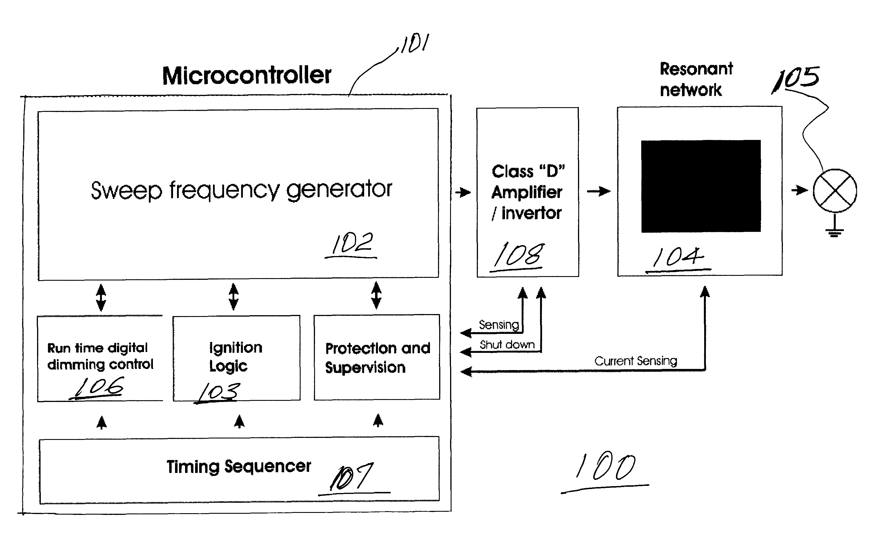
[0030]Referring to FIG. 1, an electronic ballast of a high intensity discharge lamp is denoted generally at 100. The electronic ballast may comprise a separate unit electrically coupled to the lamp, or may be enclosed in a unitary lamp module.

[0031]Upon power-up the sweep frequency generator 102 within microcontroller 101 is controlled by ignition logic 102 to sweep through a range of frequencies in order to detect a resonant frequency in the resonant ignition network 104 of high intensity discharge lamp 105. Sweep frequency generator 102 may comprise a voltage controlled oscillator, for instance.

[0032]If resonance is detected, run time digital control 106 commences, and maintains the power to lamp 105 according to the power profile provided by timing sequencer 107.

[0033]Resonant ignition network 104 transmits power for the ignition process in the lamp 105, and in general regulates current and voltage applied to the lamp, aided by amplifier / inverter 108.

[0034]If the lamp 105 fails t...


PUM


Abstract

A high intensity discharge lamp, such as a high power sodium or metal halide lamp, having an electronic ballast. The electronic ballast may incorporate resonance-based circuitry for achieving an ignition state via a frequency sweeping step, the particular ignition voltage being inherent to the operational state of the high intensity discharge lamp. The operating state of the lamp may be sensed in order to apply power and voltage levels appropriate for steady state operation.

Description

FIELD OF THE INVENTION[0001]The present invention relates generally to high intensity discharge lamps, including high power sodium and metal halide lamps, using an electronic ballast.BACKGROUND OF THE INVENTION[0002]High Intensity Discharge (HID) lamps are high-efficiency lamps used to generate high levels of lighting from a relatively small source, especially for industrial and infrastructure lighting applications. The term “HID lamp” may include mercury vapor lamps, metal halide lamps, and high pressure sodium lamps. Metal halide lamps, for instance, are commonly used in large spaces that require a high level of brightness at relatively low cost.[0003]Typical construction of a HID lamp comprises a pair of electrodes, constructed of a refractory metal such as tungsten, enclosed within an arc bulb containing a pressurized gas. In steady operation of the HID lamp, light is generated by the hot gas creating a plasma discharge when an electrical current is conducted through the gas, be...

Claims


Application Information

Patent Timeline
IPC IPC(8): G05F1/00
CPCH05B41/2882Y02B20/204Y02B20/00
Inventor ROMAN, DANIEL
Owner 2197611 ONTARIO
Learn More