
Power reduction techniques for components in integrated circuits

a technology of power reduction and integrated circuit, which is applied in the direction of power supply for data processing, liquid/fluent solid measurement, instruments, etc., can solve the problems of ineffective optimization techniques and conventional techniques for optimizing the power used in integrated circuits, and the implementation of no optimization technique for minimizing the power used by multipliers, etc., to achieve efficient and cost-effective solutions, optimize the power used in integrated circuits, and reduce power.

Active Publication Date: 2011-09-06
ALTERA CORP
View PDF11 Cites 0 Cited by
  • Summary
  • Abstract
  • Description
  • Claims
  • Application Information

AI Technical Summary

Benefits of technology

This method effectively reduces power consumption in integrated circuits without sacrificing speed or area, leading to significant power savings, especially in digital signal processing applications, and enables more efficient cooling solutions and longer battery life in portable devices.

Problems solved by technology

However, conventional techniques and mechanisms for optimizing power used in an integrated circuit are limited.
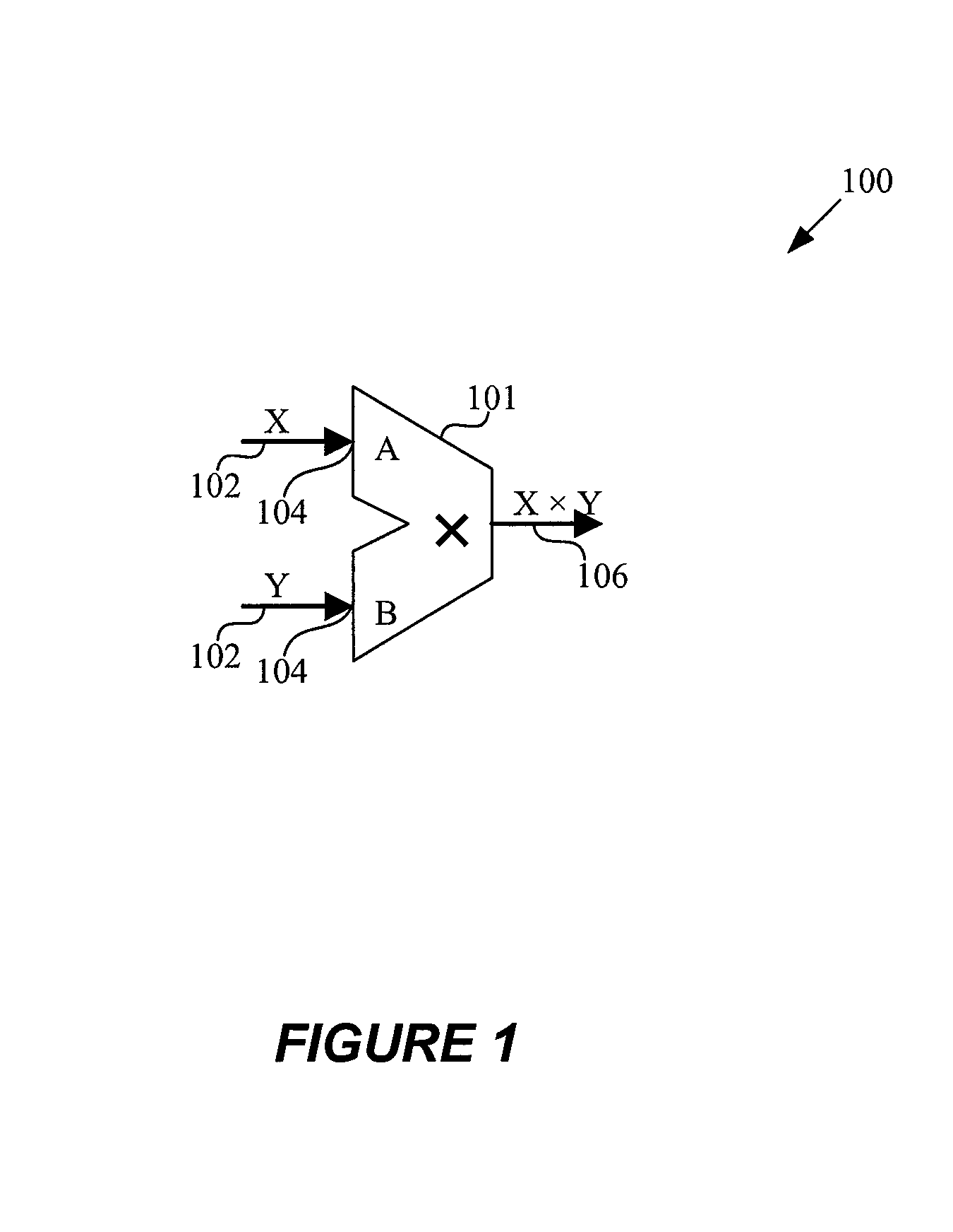
No optimization technique for minimizing the power used by the multipliers is implemented.

Method used


Image

  • Power reduction techniques for components in integrated circuits
  • Power reduction techniques for components in integrated circuits
  • Power reduction techniques for components in integrated circuits

Examples


Embodiment Construction

[0033]Reference will now be made in detail to some specific embodiments of the invention including the best modes contemplated by the inventors for carrying out the invention. Examples of these specific embodiments are illustrated in the accompanying drawings. While the invention is described in conjunction with these specific embodiments, it will be understood that it is not intended to limit the invention to the described embodiments. On the contrary, it is intended to cover alternatives, modifications, and equivalents as may be included within the spirit and scope of the invention as defined by the appended claims.

[0034]For instance, the techniques of the present invention will be described in the context of particular circuit components and design automation tools. However, it should be noted that the techniques of the present invention could be applied to a variety of circuit components and a variety of tools, including associated code provided with the tools. For example, FIGS...


PUM


Abstract

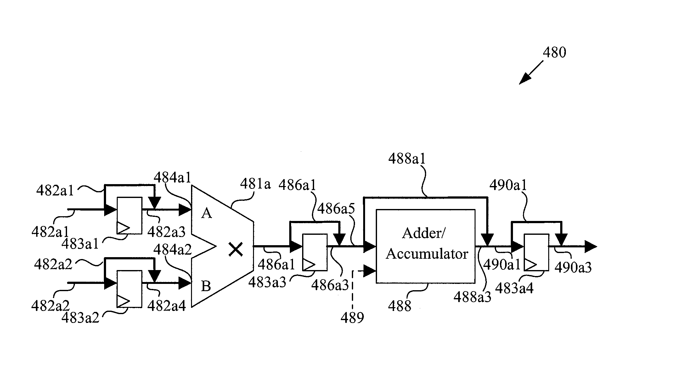
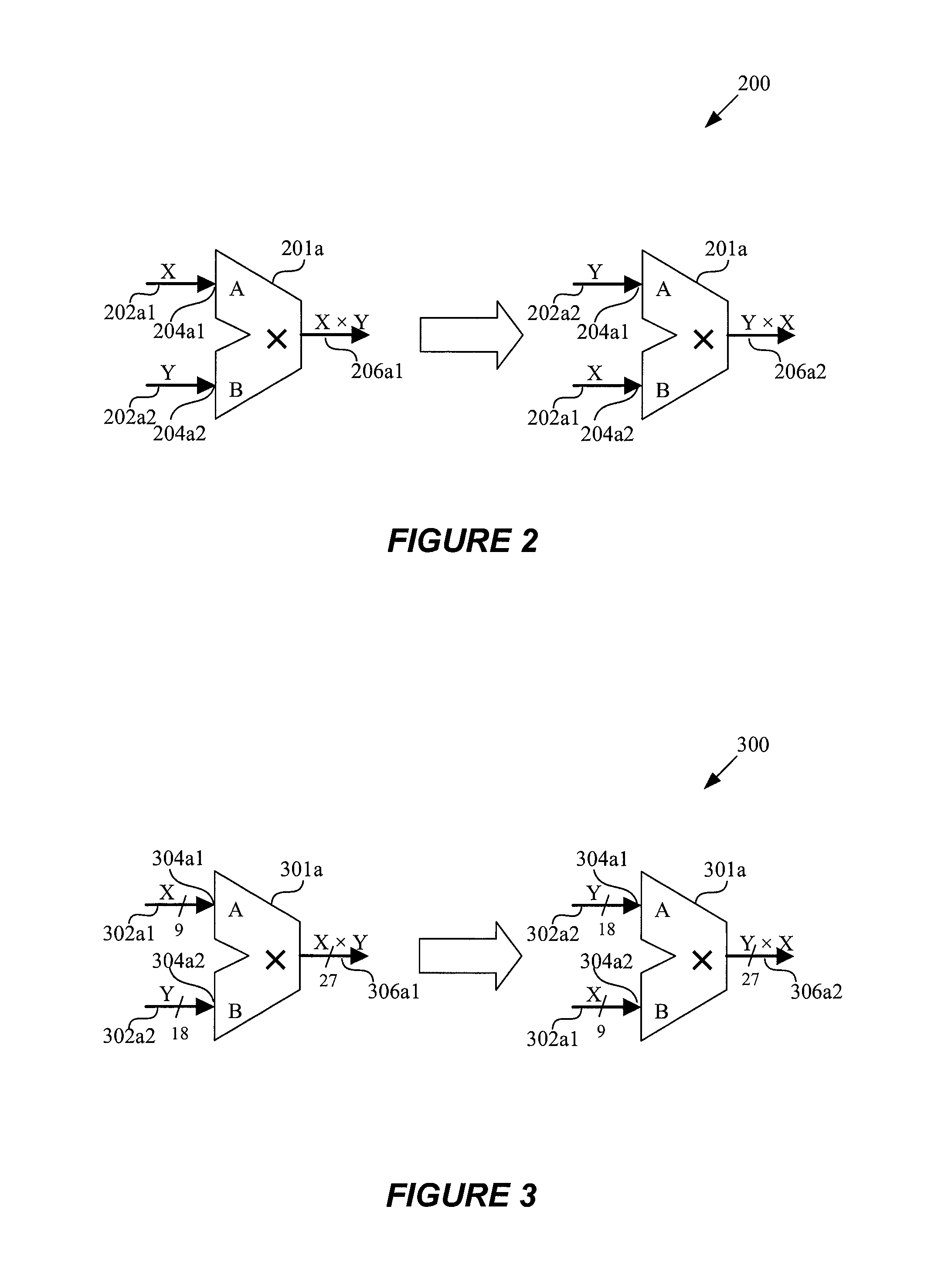
Optimizing the power used in an integrated circuit. A circuit-level transformation / permutation reduces the power consumed by multipliers or other components in integrated circuits. Signals that toggle frequently are assigned to lower power multiplier ports or the number of times a signal changes value is minimized. Large width signals are assigned to the low power port. Large multipliers are divided up and optimized as above. Pipelined multipliers are used with registers so that signals change together.

Description

CROSS REFERENCE TO RELATED APPLICATION[0001]This application is a divisional of prior application Ser. No. 11 / 431,850 filed on May 9, 2006, now pending, the disclosure of which is incorporated by reference herein in its entirety.BACKGROUND[0002]1. Field of the Invention[0003]The present invention generally relates to optimization of integrated circuits. More specifically, the invention relates to mechanisms and techniques for optimizing the power used in an integrated circuit.[0004]2. Description of Related Art[0005]Various aspects of an integrated circuit are generally optimized to improve the efficiency of the integrated circuit. For example, reducing the power consumed by various components of a circuit can reduce the amount of heat generated and improve the performance of the integrated circuit. However, conventional techniques and mechanisms for optimizing power used in an integrated circuit are limited. For example, multipliers in a circuit design are often implemented in a fi...

Claims


Application Information

Patent Timeline
Patent Type & Authority Patents(United States)
IPC IPC(8): G06F1/00G06F1/32G06F17/50
CPCG06F1/32G06F17/505G06F2217/78G06F30/327G06F2119/06
Inventor EGIER, AARON CHARLESNETO, DAVID
Owner ALTERA CORP
Learn More