
Thermal dissipating device

a heat dissipating device and heat dissipation technology, applied in the direction of semiconductor/solid-state device details, lighting and heating apparatus, laminated elements, etc., can solve the problems of heat dissipation becoming an important issue, affecting the reliability and lifetime of electronic products, and inability to maintain heat, etc., to increase the applicability and potential market potential, and the effect of versatile design

Inactive Publication Date: 2011-08-23
ORG WORLD INTPROP
View PDF1 Cites 0 Cited by
  • Summary
  • Abstract
  • Description
  • Claims
  • Application Information

AI Technical Summary

Benefits of technology

"The invention is a thermal-dissipating device that has a unique design that can be used in a wider range of applications. The device consists of multiple thermal-dissipating sheets that are connected together. Each sheet has connecting portions and thermal-dissipating fins that are connected to the connecting portions. The fins can also be connected to each other. The device can also be formed by bending the sheets once or multiple times before they are stacked or covered together. This design provides versatility and increases the potential market for the device."

Problems solved by technology

However, they also generate more heat that may result in instability of the electronic products.
The instability can affect the reliability and lifetime of the electronic products.
Therefore, heat dissipation has become an important issue of electronic products, and thermal-dissipating devices are commonly used for dissipating heat.
However, the structure of the conventional thermal-dissipating device limits its design, and thus no new design of the thermal-dissipating device is invented recently.

Method used


Image

  • Thermal dissipating device
  • Thermal dissipating device
  • Thermal dissipating device

Examples


first embodiment

Single-Folded and Single-Sided

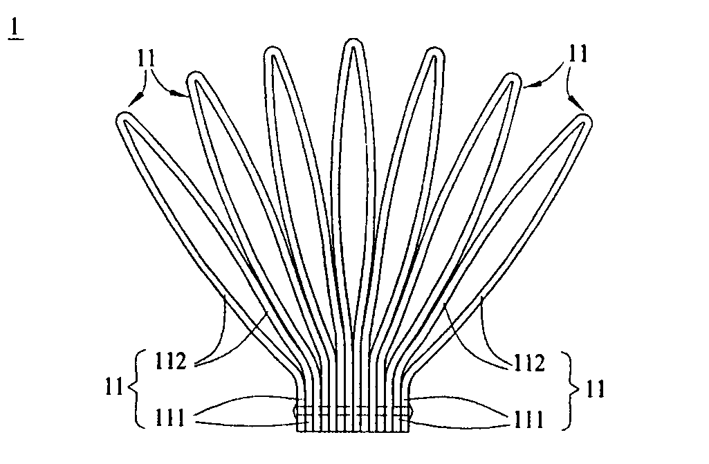
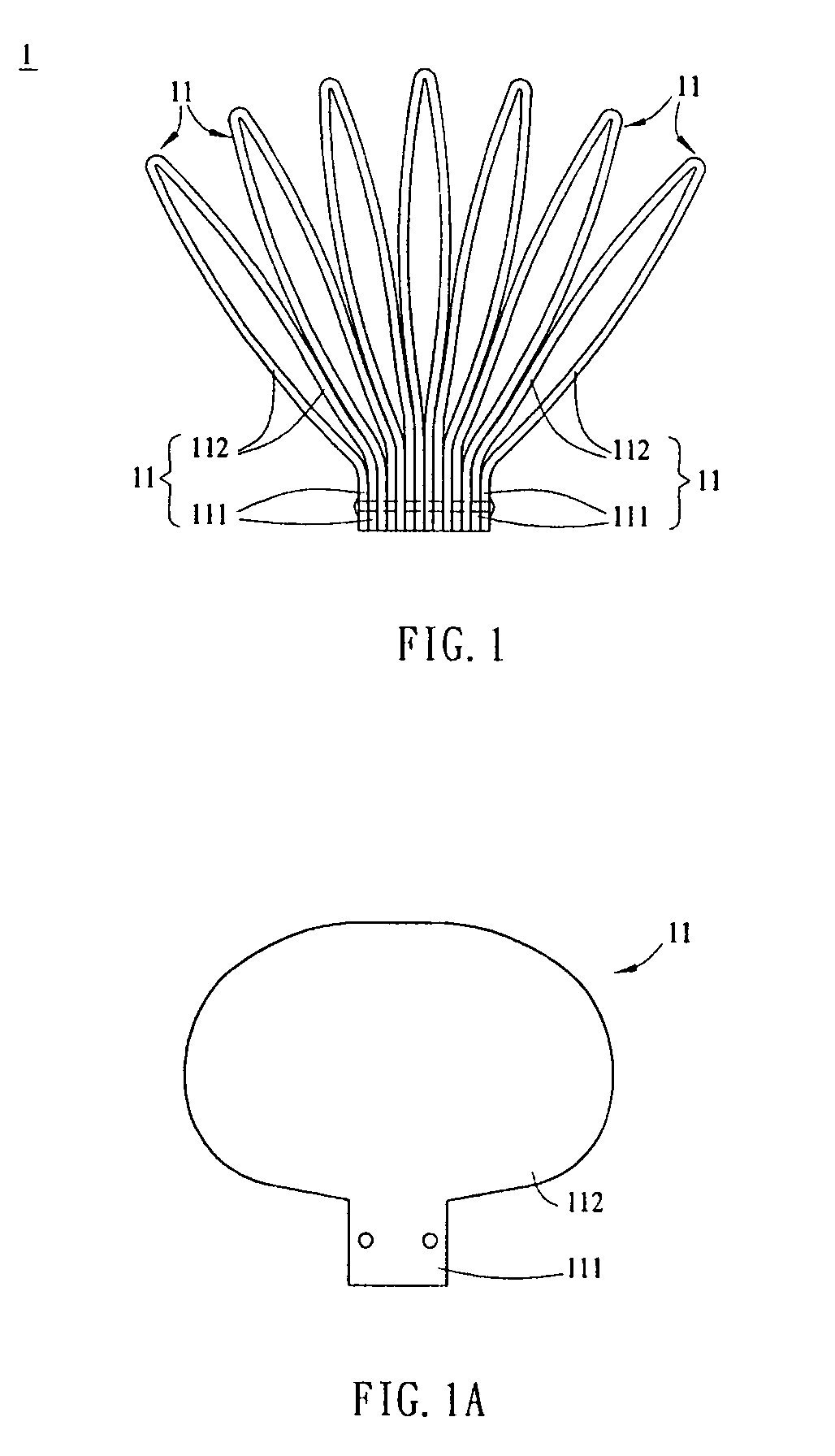
[0029]FIG. 1 is a side view of the thermal-dissipating device 1 according to a first embodiment of the invention. The thermal-dissipating device 1 includes a plurality of thermal-dissipating sheets 11, each of which has two connecting portions 111 and two thermal-dissipating fins 112. The connecting portions 111 are located on two ends of the thermal-dissipating sheet 11. The thermal-dissipating fins 112 are connected with the connecting portions 111, respectively, and extended from the connecting portions 111 outwards. The connecting portions 111 are connected with each other by screwing or riveting. This embodiment uses the riveting connection as an example. At least one set of the thermal-dissipating fins 112 are connected with each other.

[0030]As shown in FIG. 1, the thermal-dissipating device 1 has, for example but not limited to, seven sets of thermal-dissipating fins 112, and each set includes two thermal-dissipating fins 112. In practice, the th...

second embodiment

Single-Folded, Double-Layered, and Single-Sided

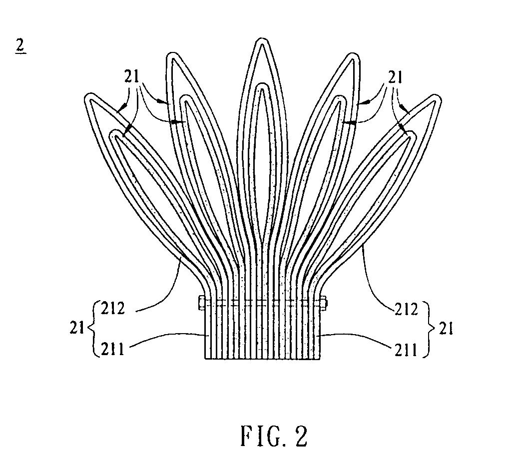
[0033]FIG. 2 is a side view of a thermal-dissipating device 2 according to the second embodiment of the invention. The difference between this thermal-dissipating device 2 and the thermal-dissipating device 1 in the first embodiment is that the thermal-dissipating sheets 21 of the thermal-dissipating device 2 are combined to provide a double-layered structure. In this embodiment, two thermal-dissipating sheets 21 of different sizes are disposed along the same direction to form a set of double-layered thermal-dissipating sheets 21. Several sets of thermal-dissipating sheets 21 are then stacked and connected by, for example, screwing. Of course, they can be disposed along different directions as well.

third embodiment

Single-Folded, Double-Layered, and Double-Sided

[0034]FIG. 3 is a top view of a thermal-dissipating device 3 according to the third embodiment of the invention. The difference between the thermal-dissipating device 3 and the thermal-dissipating device 2 is that the connecting portion 311 of the thermal-dissipating sheet 31 in the thermal-dissipating device 3 is located at the central portion of the thermal-dissipating sheet 31. The thermal-dissipating sheets 31 are further bent one more time before they are connected so as to form a double-sided, double-layered structure.


PUM


Abstract

A thermal-dissipating device is made by connecting a plurality of thermal-dissipating sheets with each other. The thermal-dissipating sheets include a plurality of connecting portions and a plurality of thermal-dissipating fins. The connecting portions are connected with each other. The thermal-dissipating fins are connected with the connecting portions, respectively. At least one set of the thermal-dissipating fins are connected with each other.

Description

BACKGROUND OF THE INVENTION[0001]1. Field of Invention[0002]The invention relates to a thermal-dissipating device.[0003]2. Related Art[0004]Recently, the electronic products usually have high performance, high operating frequencies, high speeds, and more compact sizes. However, they also generate more heat that may result in instability of the electronic products. The instability can affect the reliability and lifetime of the electronic products. Therefore, heat dissipation has become an important issue of electronic products, and thermal-dissipating devices are commonly used for dissipating heat.[0005]A conventional thermal-dissipating device has a plurality of thermal-dissipating sheets connecting with each other. Each of the thermal-dissipating sheets has a connecting portion and a thermal-dissipating fin. The thermal-dissipating fin is extended outwardly from one side of the connecting portion. During the assembling process, the thermal-dissipating sheets are connected side by s...

Claims


Application Information

Patent Timeline
Patent Type & Authority Patents(United States)
IPC IPC(8): F28F7/00
CPCF28F3/025H01L23/3672F28F2215/00H01L2924/0002H01L2924/00
Inventor KUO, CHING-SUNG
Owner ORG WORLD INTPROP
Learn More