System and method for measuring deformation of an object in a fluid tunnel

Active Publication Date: 2011-08-16
THE BOEING CO
View PDF4 Cites 44 Cited by
  • Summary
  • Abstract
  • Description
  • Claims
  • Application Information

AI Technical Summary

Benefits of technology

[0017]The technical effects of the disclosed embodiments include an improvement in the accuracy by which the attitude and / or position of the test article may be determined such that measurement of forces and moments acting on the test article may be accurately correlated to the actual attitude and / or position of the test article. In this regard, the monitoring system as disclosed herein reduces uncertainties in measurements of the attitude and / or position of the test article in order to yield highly accurate information response to aerodynamic loading or other types of loading. Advantageously, the monitoring system reduces the amount of time required to configure the test article and the fluid tunnel for testing due to the non-contact nature of the monitoring system.
[0018]In this regard, the monitoring system is less intrusive than prior art methods for measuring the attitude and position of test articles while providing improved reliability. Furthermore, the monitoring system as disclosed herein reduces the amount of time and cost required for calibrating the attitude measurement instrumentation with the force and moment instrumentation as compared to conventional monitoring systems. A further advantage provided by the monitoring system is the capability for recording and storing the positional data for post-run analyses of model attitude, position, deformation and other data acquired during testing.
[0023]Advantageously, the scanning system is further adapted to monitor the attitude, position and / or deformation of the support mechanism such as the sting extending from the aft end of the aircraft. The scanning system may be configured to scan the support mechanism while simultaneously scanning the test article. The computer system may be operative to detect any deflection such as bending that may occur in the test article and / or support system as may be the result of aerodynamic loading induced in the test article and which may be transmitted to the sting and which may cause the sting to deflect. Likewise, the scanning system may be configured to scan the tunnel walls while scanning the test article and support mechanism in order to detect and measure displacement of the tunnel walls as may occur in response to fluid flowing through the fluid tunnel or as a result of vibration due to machinery. Such displacement in the tunnel walls may have an effect on the accuracy of the positional data of the test article. In this regard, the displacement of the tunnel walls and deflection of the support mechanism may be incorporated into the support control logic in combination with other tunnel parameters in order to accurately control the attitude and position of the test article.

Problems solved by technology

Although potentiometers are generally suitable for indicating the attitude of the aircraft, they possess certain limitations which may reduce accuracy with which attitude is measured.
Because of their mounting arrangement, potentiometers may be incapable of measuring sting deflection which may compromise the accuracy of aircraft attitude measurements.
Accuracy of attitude measurements may further be compromised as a result of mechanical movement or hysteresis in structure connecting the support mechanism to the sting or the sting to the aircraft.
Unfortunately, the use of photogrammetry or videogrammetry as described above is computationally intensive due to the large number of cameras (e.g., eight cameras) required and the need to calibrate the positions of the cameras relative to the wind tunnel.
Furthermore, photogrammetric and videogrammetric applications lack the ability for real-time visualization of the test article during wind tunnel operation.

Method used


Image

  • System and method for measuring deformation of an object in a fluid tunnel
  • System and method for measuring deformation of an object in a fluid tunnel
  • System and method for measuring deformation of an object in a fluid tunnel

Examples


Embodiment Construction

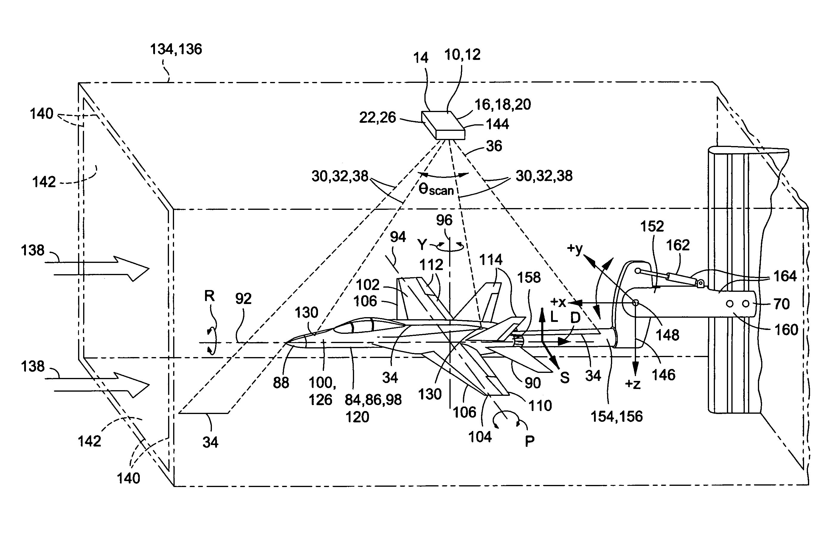
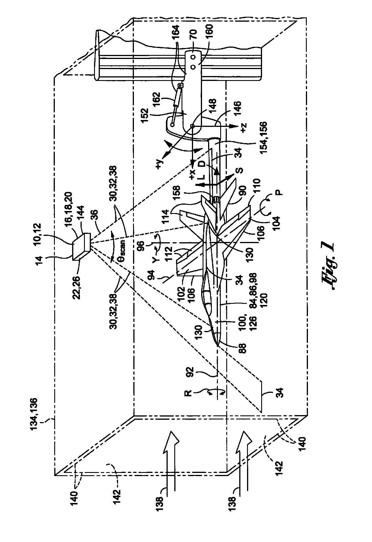
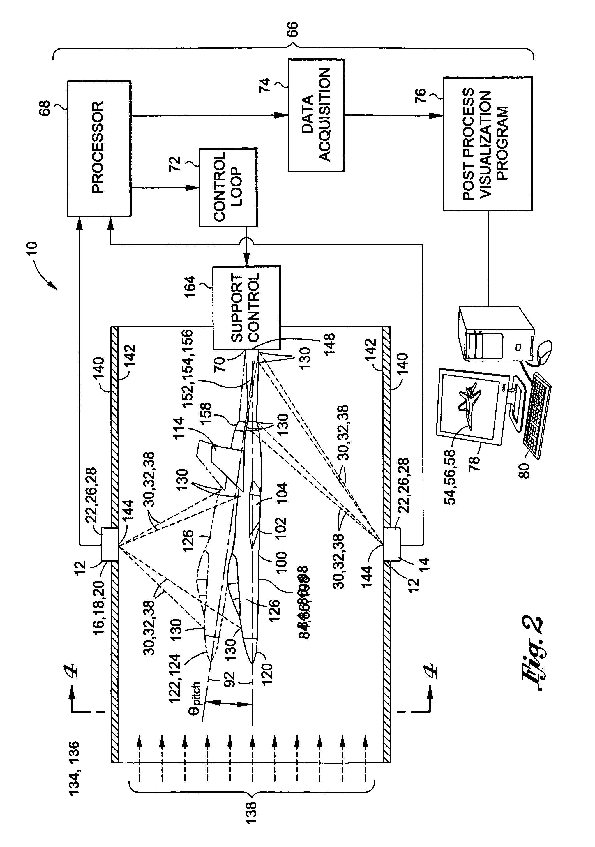
[0041]Referring now to the drawings wherein the showings are for purposes of illustrating preferred and various embodiments of the disclosure only and not for purposes of limiting the same, shown in FIG. 1 is a monitoring system 10 as may be used for monitoring an object such as a test article 84 in a fluid tunnel 134 such as a wind tunnel 136. In a broad sense, the monitoring system 10 may comprise a scanning system 12 and a computer system 66 in communication with the scanning system 12. The scanning system 12 may comprise any suitable optical sensor 14 including, but not limited to, a laser scanner 16 for scanning surfaces of objects or test articles 84 and measuring and recording positional data of a plurality of points on the test article 84 surfaces. The computer system 66 receives the positional data regarding the plurality of points (i.e., the shape of the object) and is operative to determine parameters of the test article 84 including, without limitation, the attitude, pos...


PUM


Abstract

A monitoring system for monitoring a test article includes a scanning system and a computer system. The test article may be positioned within a fluid tunnel. The scanning system may be configured to scan the test article and record positional data of at least one point on an article surface of the test article. The computer system is in communication with the scanning system for receiving the positional data and being operative to determine at least one of the following: a position of the test article, an attitude of the test article, and deformation of the article surface.

Description

CROSS-REFERENCE TO RELATED APPLICATIONS[0001](Not Applicable)STATEMENT RE: FEDERALLY SPONSORED RESEARCH / DEVELOPMENT[0002](Not Applicable)FIELD[0003]The present disclosure relates generally to measurement systems and, more particularly, to a system for monitoring position, attitude and / or deformation of an object in a fluid tunnel.BACKGROUND[0004]Fluid tunnels are used in a variety of applications to measure the effects of fluid flow over an object. For example, in aerodynamic testing, wind tunnels are used to measure the response of a test article such as a scale model aircraft to air passing over the aircraft. The wind tunnel provides a means to evaluate the test article in a controlled environment under conditions that are dynamically similar to conditions to which a full-size version of the aircraft may be subjected in actual flight. Air in the wind tunnel flows over the scale model aircraft at a controlled speed in order to evaluate the aerodynamic response of the scale model ai...

Claims


Application Information

Patent Timeline
IPC IPC(8): G01M9/00
CPCG01M9/04G01M9/062G01M9/08G01M11/083
Inventor STONNER, DONNA E.GOODMAN, RONALD L.BENNE, MICHAEL E.
Owner THE BOEING CO
Why Eureka
Try Eureka