
Integrated test waveform generator (TWG) and customer waveform generator (CWG), design structure and method

a technology of integrated test waveform generator and customer waveform generator, which is applied in the direction of generating/distributing signals, instruments, pulse techniques, etc., can solve the problems of significant area cost, inability to match at-speed structural test (asst) operations with end-user functional operations, and inability to detect skews in clock signal inputs

Inactive Publication Date: 2011-08-09
GLOBALFOUNDRIES INC
View PDF3 Cites 10 Cited by
  • Summary
  • Abstract
  • Description
  • Claims
  • Application Information

AI Technical Summary

Benefits of technology

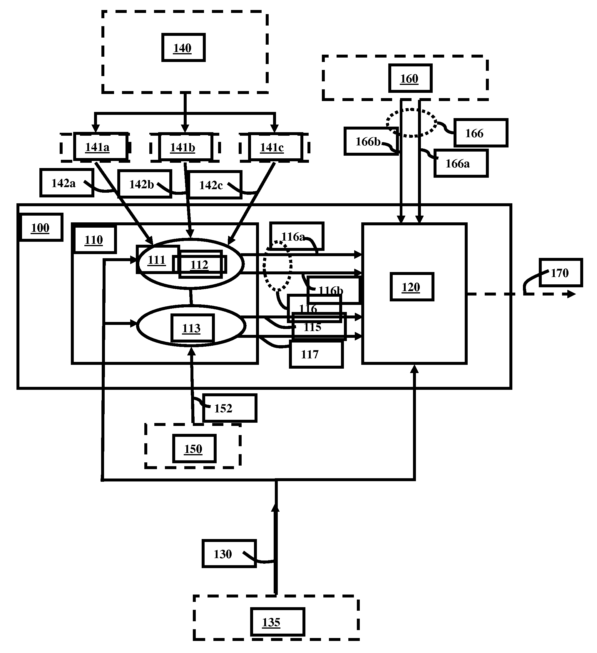
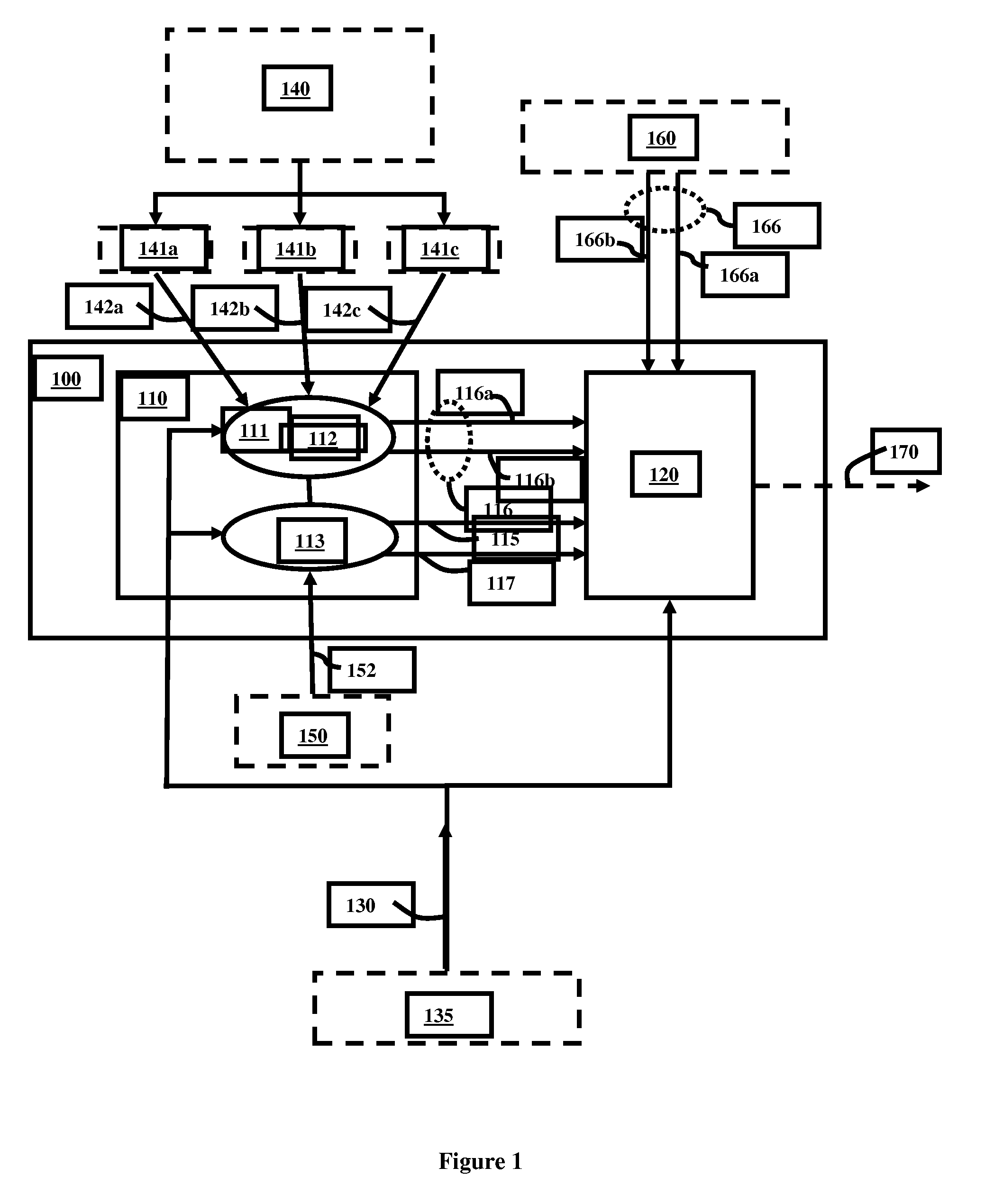
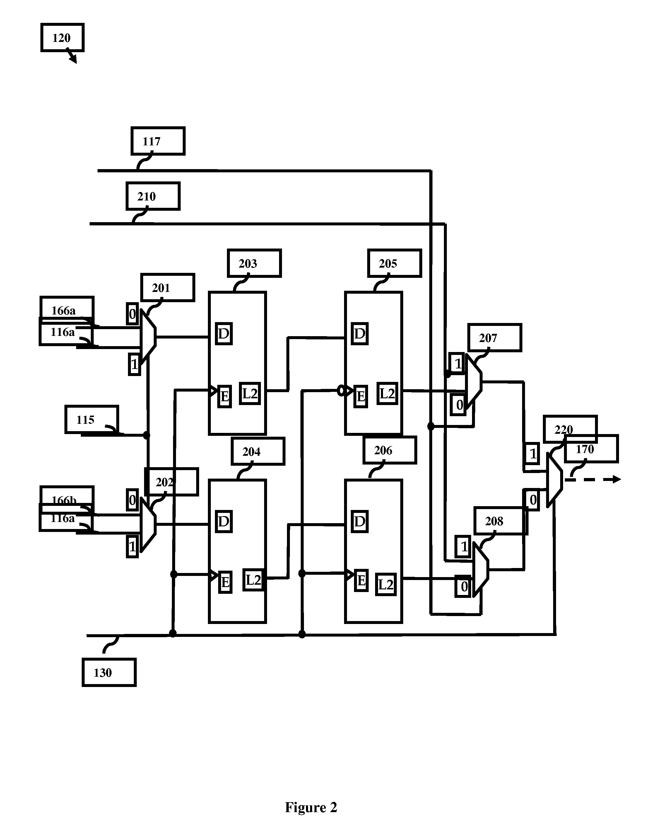
The patent describes a clock generation circuit that can generate an output clock signal that is synchronized with an input clock signal. The circuit includes a deskewer circuit that can selectively gate the input clock signal with waveform signals generated by either an internal waveform generator or an external waveform generator. The deskewer circuit can generate the required output clock signal by selectively gating the input clock signal with the waveform signals and processing them through a series of latches and a multiplexer. The circuit can also receive user-supplied output clock signal specifications for testing and functional operations. The technical effect of this invention is to provide a more precise and versatile clock generation circuit for testing and functional operations.

Problems solved by technology

Milton further discloses that, when multiple clock generators are utilized to feed clock signals to different digital logic circuits within an integrated circuit structure, a difference in delay time (i.e., skew) among the clock signal inputs to various digital circuits inevitably results.
The requirement for separate testing and functional clock generation circuits results in significant area costs and limits the matching of at-speed structural test (ASST) operations with end-user functional operations.

Method used


Image

  • Integrated test waveform generator (TWG) and customer waveform generator (CWG), design structure and method
  • Integrated test waveform generator (TWG) and customer waveform generator (CWG), design structure and method
  • Integrated test waveform generator (TWG) and customer waveform generator (CWG), design structure and method

Examples


Embodiment Construction

[0021]The embodiments of the invention and the various features and advantageous details thereof are explained more fully with reference to the non-limiting embodiments that are illustrated in the accompanying drawings and detailed in the following description. It should be noted that the features illustrated in the drawings are not necessarily drawn to scale. Descriptions of well-known components and processing techniques are omitted so as to not unnecessarily obscure the embodiments of the invention. The examples used herein are intended merely to facilitate an understanding of ways in which the embodiments of the invention may be practiced and to further enable those of skill in the art to practice the embodiments of the invention. Accordingly, the examples should not be construed as limiting the scope of the embodiments of the invention.

[0022]As mentioned above, separate and discrete clock generation circuits are typically used for testing operations and for functional operation...


PUM


Abstract

Disclosed are embodiments of a clock generation circuit, a design structure for the circuit and an associated method that provide deskewing functions and that further provide precise timing for both testing and functional operations. Specifically, the embodiments incorporate a deskewer circuit that is capable of receiving waveform signals from both an external waveform generator and an internal waveform generator. The external waveform generator can generate and supply to the deskewer circuit a pair of waveform signals for functional operations. The internal waveform generator can be uniquely configured with control logic and counter logic for generating and supplying a pair of waveform signals to the deskewer circuit for any one of built-in self-test (BIST) operations, macro-test operations, other test operations or functional operations. The deskewer circuit can selectively gate an input clock signal with the waveform signals from either the external or internal waveform generator in order to generate the required output clock signal.

Description

FIELD OF THE INVENTION[0001]The embodiments of the invention generally relate to waveform generators, and, more particularly, to an integrated clock generation circuit for test operations and functional operations, an associated design structure and an associated method.DESCRIPTION OF THE RELATED ART[0002]Clock generation circuits provide precise timing to allow digital circuits to work properly during functional operations. A typical clock generation circuit generates an output clock signal with a series of high and low pulses at a fixed frequency. The rising and falling edges of the output clock signal are then used as a reference for critical actions within digital circuits. For example, they can be used to synchronize bus cycles or initiate data operations (e.g., as discussed in U.S. Pat. No. 6,507,230 of Milton et. al., issued on Jan. 14, 2003 and incorporated herein by reference). Milton further discloses that, when multiple clock generators are utilized to feed clock signals ...

Claims


Application Information

Patent Timeline
Patent Type & Authority Patents(United States)
IPC IPC(8): G06F17/50
CPCG06F1/10G06F17/505H03K5/156G06F2217/62G06F30/327G06F30/396G06F2117/04
Inventor GRISE, GARY D.IYENGAR, VIKRAMLACKEY, DAVID E.MILTON, DAVID W.
Owner GLOBALFOUNDRIES INC
Learn More