
Single motor electro wedge brake system using solenoid mechanism for implementing additional functions

a single-motor, electro-wedge technology, applied in the direction of braking systems, mechanical equipment, slack adjusters, etc., can solve the problems of complicated structure limited improvement in the stability inability to help with the complicated structure of the hydraulic brake, so as to improve the assembly property of the electro-wedge brake, reduce the size of the entire electro-wedge brake, and reduce the number of parts

Inactive Publication Date: 2011-08-02
HYUNDAI MOBIS CO LTD
View PDF16 Cites 2 Cited by
  • Summary
  • Abstract
  • Description
  • Claims
  • Application Information

AI Technical Summary

Benefits of technology

The present invention provides an electro wedge brake system that uses a single motor to implement various additional functions, such as maintaining a set clearance of a pad, a Fail-Safe function, and an electric parking brake function. The system includes an electric pedal, an ECU, wedge calipers, wedge actuator assemblies, and housings. The use of a solenoid mechanism interlocked with the motor reduces the size of the entire brake system and simplifies the structure of related parts. The system also includes an auxiliary power supply circuit and an auxiliary battery in the ECU. The braking motor unit includes a motor, a linear motion converter, and an interlocking rod. The wedge braking unit includes a connecting rod, a wedge moving plate, a wedge base plate, and a wedge roller. The solenoid mechanism includes an adjusting unit, a solenoid unit, and an EPB spring. The system helps improve assembly properties, reduce manufacturing costs, and reduce weight of the brake system.

Problems solved by technology

For this reason, the hydraulic brake cannot help having a complicated structure including a master cylinder that is operated by a booster for increasing a force applied to a pedal to generate hydraulic pressure, hydraulic pressure lines connected to a wheel cylinder, and various devices that control and assist the cylinders and lines.
Accordingly, improvement in the stability of the hydraulic brake is limited due to the complicated structure and deterioration in the reliability of a braking performance, which is caused by use of hydraulic pressure.
For this reason, the entire structure of the EWB becomes complicated.
Since the EWB uses two motors to separately generate power, the size of the EWB cannot help being increased due to a space for a motor.
The increase in size causes limitation in assembling the EWB at the wheel.

Method used


Image

  • Single motor electro wedge brake system using solenoid mechanism for implementing additional functions
  • Single motor electro wedge brake system using solenoid mechanism for implementing additional functions
  • Single motor electro wedge brake system using solenoid mechanism for implementing additional functions

Examples


Embodiment Construction

[0042]A preferred embodiment of the present invention will be described in detail below with reference to the accompanying drawings.

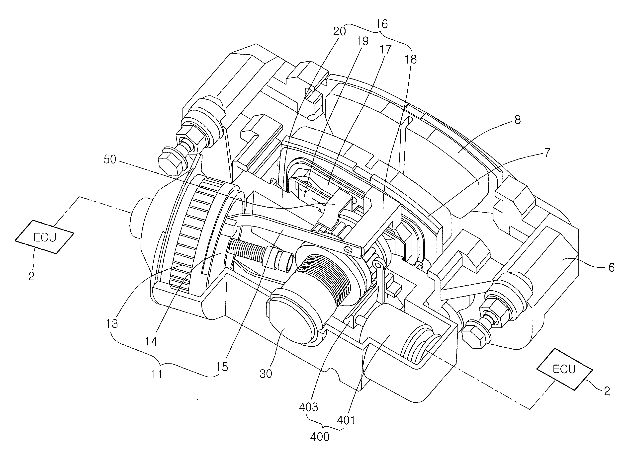
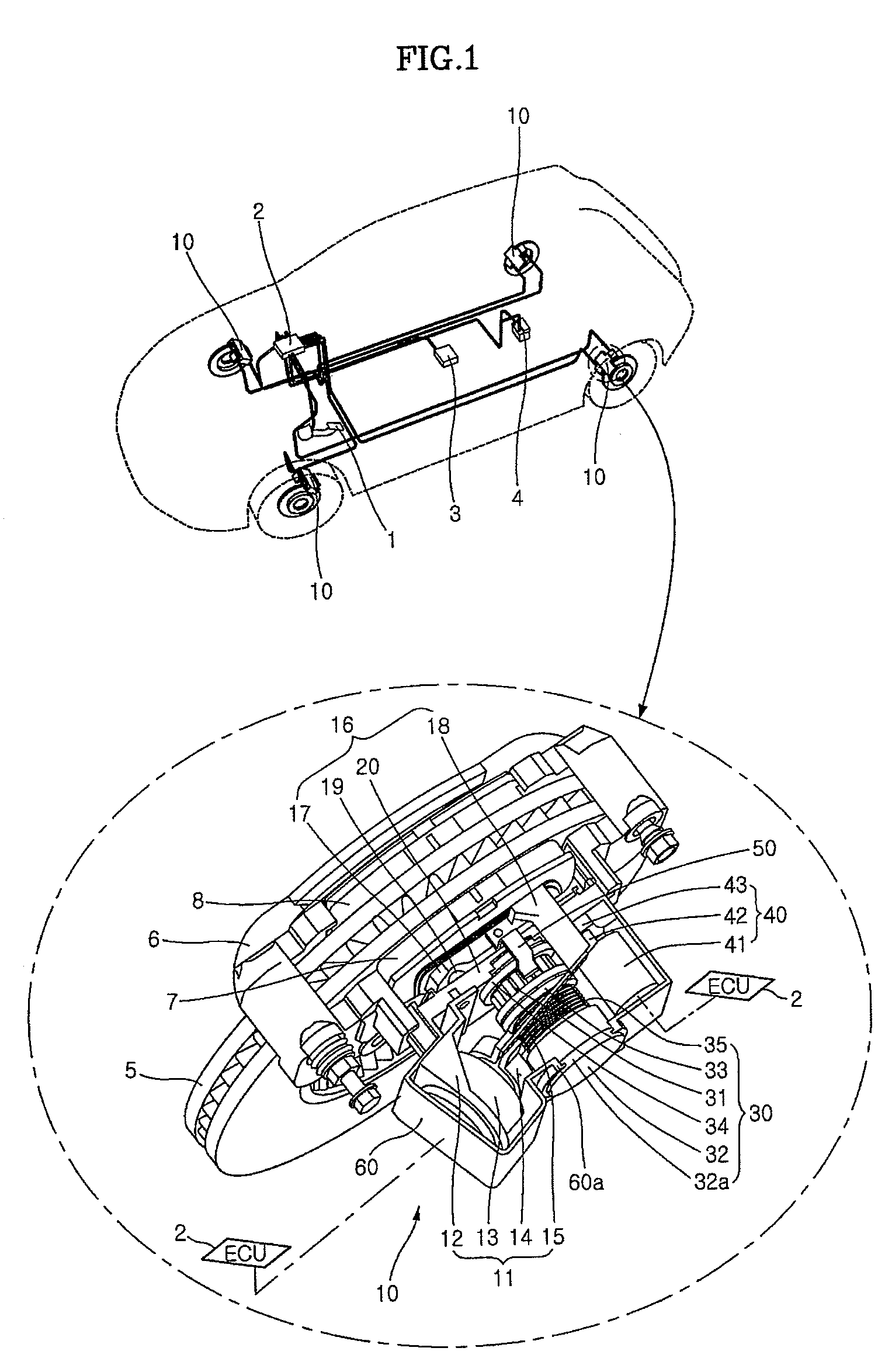
[0043]FIG. 1 is a view of a single motor electro wedge brake system, which uses a solenoid mechanism to implement additional functions, according to an embodiment of the present invention. The single motor electro wedge brake system according to an embodiment of the present invention includes an electric pedal 1, an ECU 2, wedge calipers 6, and wedge actuator assemblies 10. Electric pedal 1 is operated by a driver to brake a vehicle. ECU 2 performs control in consideration of information about the vehicle when the vehicle is braked. Each of wedge calipers 6 presses a disk 5, which rotates together with a wheel, to brake the vehicle. Each of wedge actuator assemblies 10 perform braking by pressing a pad against disk 5 using power, which is generated by one motor 13 controlled by ECU 2, during the braking. Further, each of wedge calipers 6 includes a sole...


PUM


Abstract

The present invention provides an electro wedge brake (EWB) system that implements a main braking function by using power generated by one motor. Further, the electro wedge brake system implements various additional functions such as a function for maintaining a set clearance of a pad, a Fail-Safe function, and an EPB function, by using that the forward movement of a push rod shaft screwed using a NSL (Non-Self Locking) type screw is restrained or released on the basis of ON / OFF control of the solenoid mechanism interlocked with the main braking function motor. Accordingly, since only one motor is used to generate power, it is possible to reduce the number of parts and to simplify the structure.

Description

CROSS-REFERENCE TO RELATED APPLICATIONS[0001]The present application is based on, and claims priority from, Korean Application Serial Number 10-2007-0062110, filed on Jun. 25, 2007, the disclosure of which is hereby incorporated by reference herein in its entirety.FIELD OF THE INVENTION[0002]The present invention relates to a wedge brake system, and more particularly, to a single motor electro wedge brake system, which uses a solenoid mechanism to implement additional functions.BACKGROUND OF THE INVENTION[0003]In general, a brake system is used to decelerate, stop, or park a moving vehicle.[0004]A friction brake, which converts kinetic energy into thermal energy by using a frictional force and radiates the thermal energy to the air, is generally used in the brake system. Pads press both sides of a disk, which rotates together with a wheel, with hydraulic pressure, so that the friction brake implements a braking function.[0005]The hydraulic brake implements braking by pressing the pa...

Claims


Application Information

Patent Timeline
Patent Type & Authority Patents(United States)
IPC IPC(8): F16D55/16F16D65/14F16D65/18F16D65/22F16D65/28
CPCB60T13/741F16D65/18F16D2121/24F16D2125/40F16D2125/66F16D2127/06F16D2127/10F16D2129/08F16D65/28B60T13/74
Inventor KIM, JONGSUNG
Owner HYUNDAI MOBIS CO LTD
Learn More