
Thermal management for photovoltaic devices

a photovoltaic device and thermal management technology, applied in the field of photovoltaic devices, can solve the problems of cumbersome or expensive cooling techniques, cumbersome and expensive cooling techniques, and increase the normal operating cell temperature (noct) of solar cells, so as to increase the efficiency of cells and modules, and increase the capacity

Inactive Publication Date: 2011-07-26
AERIS CAPITAL SUSTAINABLE IP
View PDF17 Cites 93 Cited by
  • Summary
  • Abstract
  • Description
  • Claims
  • Application Information

AI Technical Summary

Benefits of technology

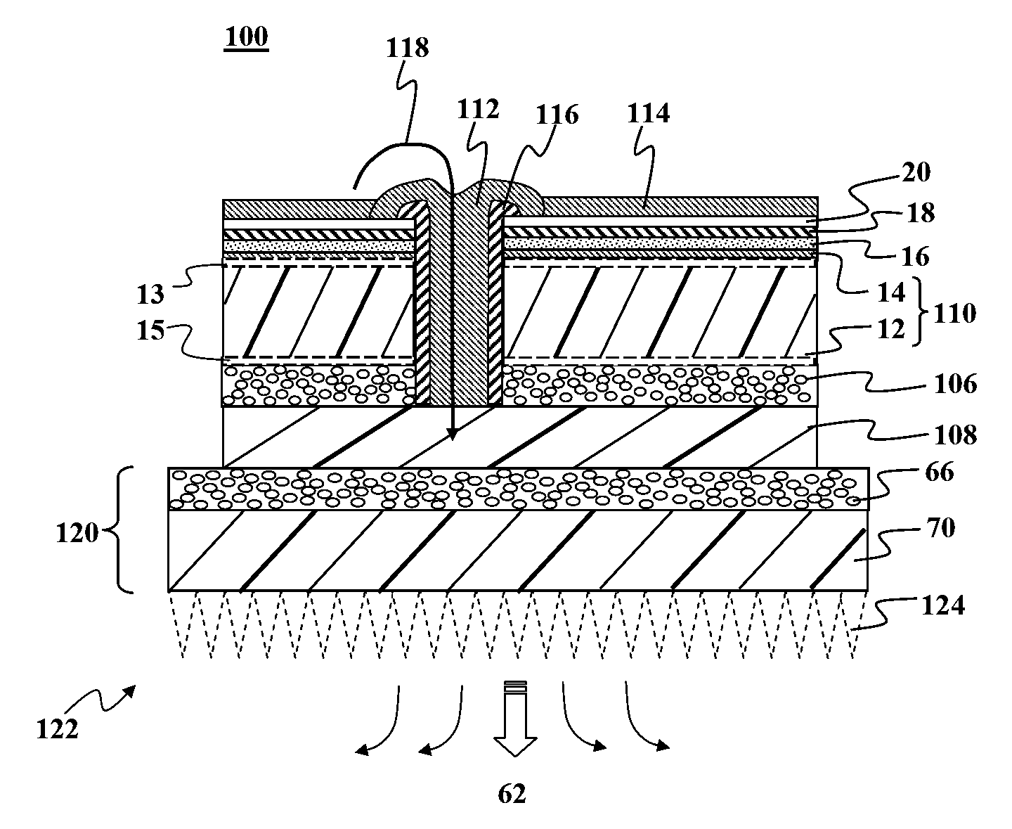
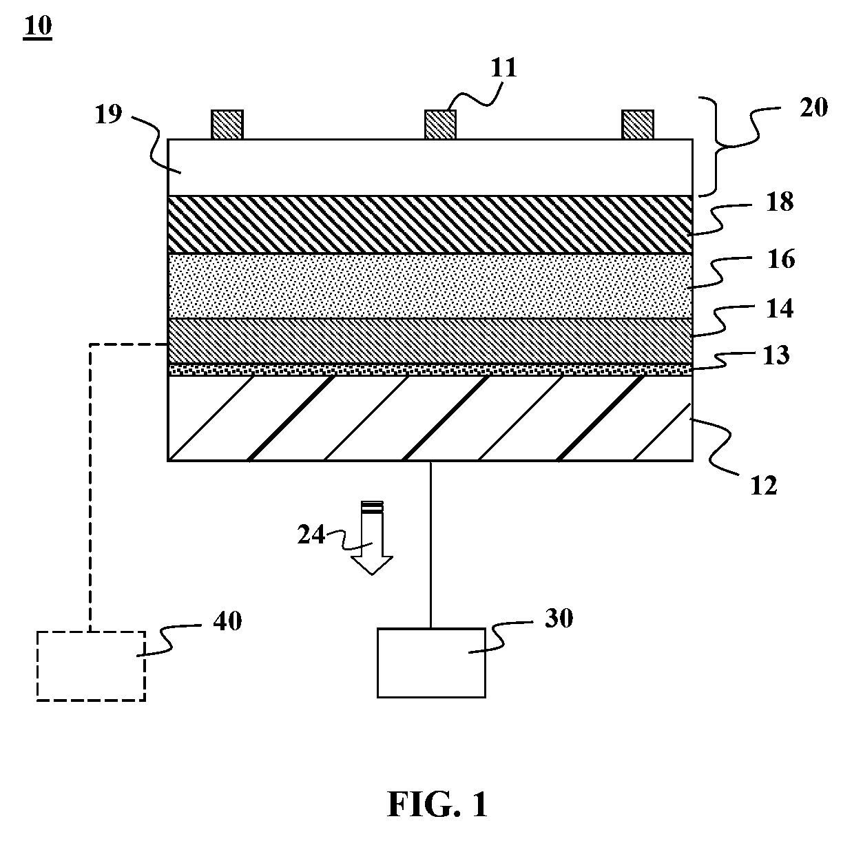
[0006]In one embodiment of the present invention, a photovoltaic device is provided that comprises of at least one photovoltaic cell based on a thin-film photovoltaic stack deposited directly onto a thermally conductive substrate. The thermally conductive substrate may be connected to a heat sink in a configuration to allow sufficient heat transfer to lower a normal operating cell temperature (NOCT) of the photovoltaic cell, thus increasing the efficiency of the cell and the module. The thermally conductive substrate may be a metal foil, which is significantly more thermally conductive than glass substrates used in traditional thin-film photovoltaic devices.
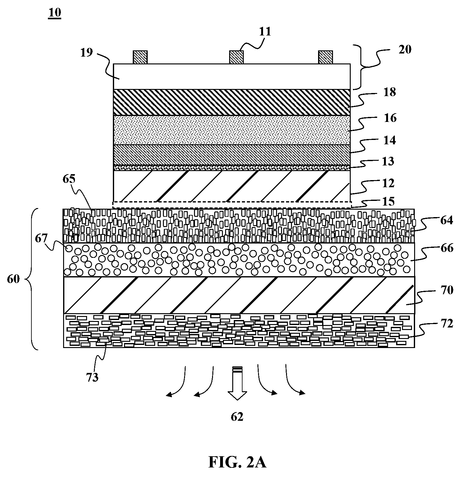
[0009]In another embodiment of the present, a photovoltaic module is provided that includes at least one photovoltaic cell mounted on a thermally conductive module support layer. The thermally conductive module support layer comprises of a thermally conductive substrate coupled to a heat sink in a manner sufficient to allow for heat transfer from the cells to the heat sink that lowers a normal operating cell temperature (NOCT) of the photovoltaic cells, thus increasing the efficiency of the cell and the module. The photovoltaic module improves heat transfer by modifying the module backsheet so that it does not trap heat and allows heat to escape. This embodiment of the present invention is not limited to thin-film solar cells and the improved module backsheet may be adapted for use with solar cells of various types of absorber layers.
[0013]In another embodiment of the present invention, a photovoltaic roofing tile may be provided comprising of a metal backplane and at least one photovoltaic cell mounted on the module support layer. The backplane may be comprised of a thermally conductive substrate that is connected to a thermal sink in a manner sufficient to allow for heat transfer from the cells to the thermal sink that lowers a normal operating cell temperature (NOCT) of the photovoltaic cells, thus increasing the efficiency of the cell and the module. The backplane may be segmented to include an active conductive element for a positive charge and another active conductive element for negative charge; wherein the backplane of the tile is electrically coupled to a backplane on another tile to form a series interconnection.
[0014]In yet another embodiment, a method according to the present invention comprises of providing at least one photovoltaic cell and mounting the photovoltaic cell directly onto a thermally conductive substrate to define a thermal path from an underside of the photovoltaic cell to a thermal sink. The thermal path is preferably of sufficient capacity to lower a normal operating cell temperature (NOCT) of the photovoltaic cell, thus increasing the efficiency of the cell and the module.
[0015]Optionally, the following may also be adapted for use with any of the embodiments disclosed herein. The heat sink may be a thermally conductive foil laminated onto the thermally conductive cell base layer using a pottant material for adhesion. The pottant layer is chosen to be thermally conductive. The thermal conductivity of the pottant layer may be obtained by keeping its thickness at less than about 75 microns. The thermal conductivity of the pottant layer may be obtained by adding thermally conductive beads to thermally not very conductive adhesive. The beads added to the pottant and / or insulating layer may be ceramics. The pottant adhesive may be EVA. The back foil provides environmental protection of the module and enables heat transfer at least two orders of magnitude more easily than glass. The surface area of the module back foil may be enhanced so as to maximize heat transfer between the back foil and the surrounding atmosphere. The surrounding atmosphere may be air, a liquid, or a liquid or a gas mix with convective transport.

Problems solved by technology

Unfortunately, increasing sunlight intensity also typically means increased normal operating cell temperature (NOCT) of the solar cell.
For solar cells and solar cell modules, excessive heat decreases the conversion efficiency of these devices.
A central challenge in finding suitable cooling techniques for solar cells and solar cell modules lies in finding solutions that are cost effective and easily integrated with the solar cell configuration.
Although it is desirable to reduce NOCT, cumbersome or expensive cooling techniques present more cost than the conversion efficiency gained by keeping the solar cells cool.
Traditional solar cell modules pose a particular challenge as the multi-layer pottants used in these modules are poor thermal conductors and do not provide an efficient thermal path for drawing thermal energy away from such solar cell modules.
The challenge is even greater for modules with traditional thin-film solar cells which present heat transfer issues at the solar cell level, prior to reaching the solar module level.
The thickness of glass substrates and the inherently low thermal conductivity of glass substrates complicate the cooling process as there is more mass to cool and the glass acts as a thermal barrier.
Mounting thin-film glass substrate solar cells in traditional module packaging further complicates matters.

Method used


Image

  • Thermal management for photovoltaic devices
  • Thermal management for photovoltaic devices
  • Thermal management for photovoltaic devices

Examples


Embodiment Construction

[0026]It is to be understood that both the foregoing general description and the following detailed description are exemplary and explanatory only and are not restrictive of the invention, as claimed. It may be noted that, as used in the specification and the appended claims, the singular forms “a”, “an” and “the” include plural referents unless the context clearly dictates otherwise. Thus, for example, reference to “a material” may include mixtures of materials, reference to “a compound” may include multiple compounds, and the like. References cited herein are hereby incorporated by reference in their entirety, except to the extent that they conflict with teachings explicitly set forth in this specification.

[0027]In this specification and in the claims which follow, reference will be made to a number of terms which shall be defined to have the following meanings:

[0028]“Optional” or “optionally” means that the subsequently described circumstance may or may not occur, so that the des...


PUM


Abstract

Methods and devices are provided for improved thermal management for photovoltaic devices and assemblies. In one embodiment, the photovoltaic device comprises of at least one photovoltaic cell based on a thin-film photovoltaic stack deposited directly onto a thermally conductive substrate. The thermally conductive substrate is connected to a heat sink in a configuration to allow sufficient heat transfer that lowers a normal operating cell temperature (NOCT) of the photovoltaic cell, thus increasing the efficiency of the cell and the module.

Description

FIELD OF THE INVENTION[0001]This invention relates generally to photovoltaic devices, and more specifically, to thermal management for solar cells, solar cell strings, and / or solar cell modules.BACKGROUND OF THE INVENTION[0002]Solar cells and solar cell modules convert sunlight into electricity. These devices are traditionally mounted outdoors on rooftops or in wide-open spaces where they can maximize their exposure to sunlight. When sunlight intensity increases, electrical output from solar cells and solar cell modules also increases. Unfortunately, increasing sunlight intensity also typically means increased normal operating cell temperature (NOCT) of the solar cell. For solar cells and solar cell modules, excessive heat decreases the conversion efficiency of these devices. NOCT for most solar cell modules is around 47° C. Many solar cell modules lose about 0.5% efficiency for every degree of increase in NOCT. A variety of factors may contribute to increased NOCT such as greater a...

Claims


Application Information

Patent Timeline
IPC IPC(8): H02N6/00H01L31/042H01L31/00
CPCH01L31/0392H01L31/049H01L31/052Y02E10/50H01L31/022441H01L31/035281H01L31/03925H01L31/03928H01L31/0504H01L31/0521H01L31/0445H02S40/36H02S40/425Y02E10/541Y02P70/50
Inventor ROSCHEISEN, MARTINADRIANI, PAUL
Owner AERIS CAPITAL SUSTAINABLE IP
Learn More