
Exercise machine with multi-function user engagement device

a multi-functional, user-friendly technology, applied in the field of exercise machines, can solve the problems of not maintaining or supporting the user in the proper position, user cannot truly isolate any one specific muscle or muscle group, and no means for properly aligning the exercise arm and user support, etc., to reduce the effect of user's body weight on the resistance felt, reducing the initial lifting resistance, and reducing the effect of the user's body weigh

Active Publication Date: 2011-07-19
HOIST FITNESS SYST
View PDF225 Cites 77 Cited by
  • Summary
  • Abstract
  • Description
  • Claims
  • Application Information

AI Technical Summary

Benefits of technology

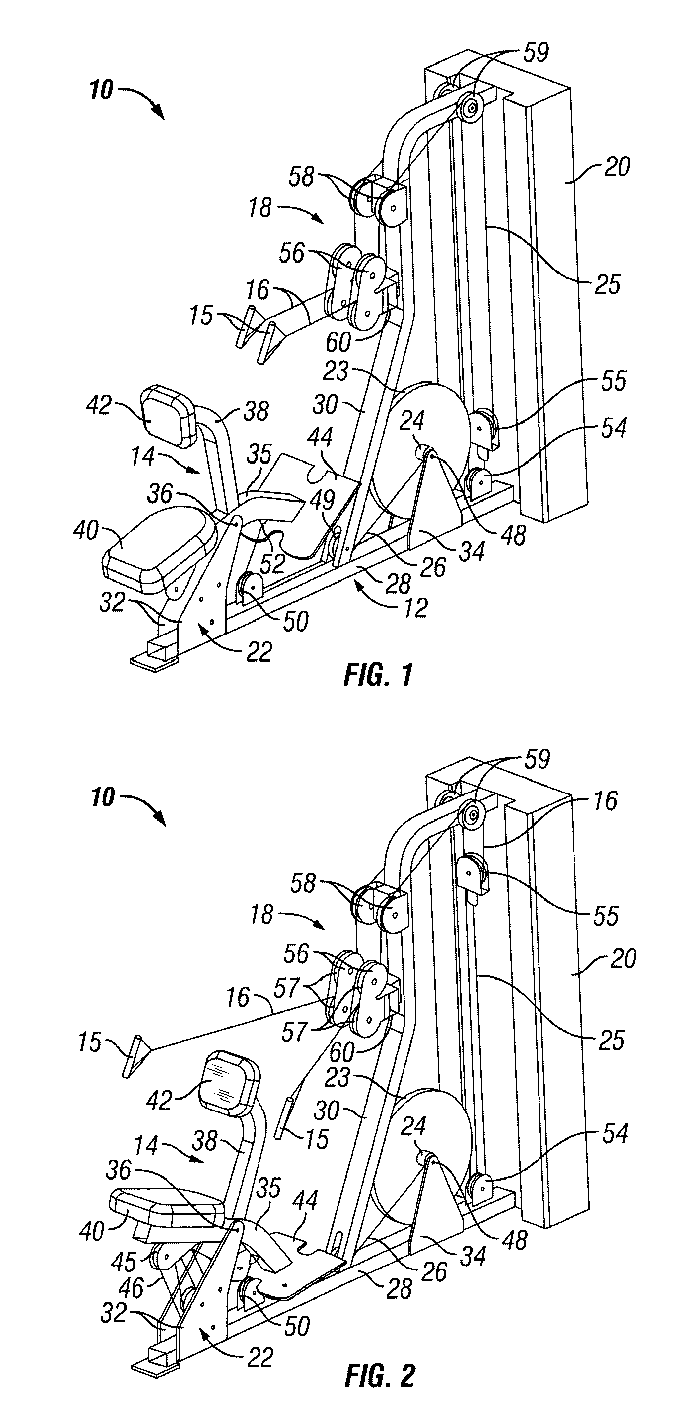
[0013]The user support frame in an exemplary embodiment has both a primary user support, such as a seat pad or back pad, and one or more secondary user supports which travel with the primary user support during an exercise. One secondary user support may be a back pad, shoulder pad, thigh hold-down pads, chest pad, or the like. Another secondary or additional user support may be a foot rest, which may be mounted on, and travel with, the user support frame. Alternatively, a foot rest may be mounted on the main frame. In either case, the foot rest provides additional stabilization to the user, helping them to maintain a proper exercise position and providing additional comfort and support. In another embodiment, the secondary user support acts as a back pad in one mode of operation, and act as a chest pad in the other mode of operation of the user engagement device. The use of multiple support pads on the user support frame helps to position the exerciser properly and safely. In one embodiment, these supports are in fixed alignment to each other and travel together, keeping the user in the same braced position throughout the entire exercise range of motion. This allows the user to focus on the exercise rather than worrying about their positioning on a moving platform or seat.
[0016]A pivot assembly which pivotally supports the user support frame may be located beneath the user support frame. The connecting linkage may be rigid, flexible, or partially flexible, and may be adjustable in length or position. The user engagement device or exercise arm may have one or two handles. If handles are provided, they may be rigid or flexible, fixed or self-aligning, and may provide two dimensional or three dimensional movement.
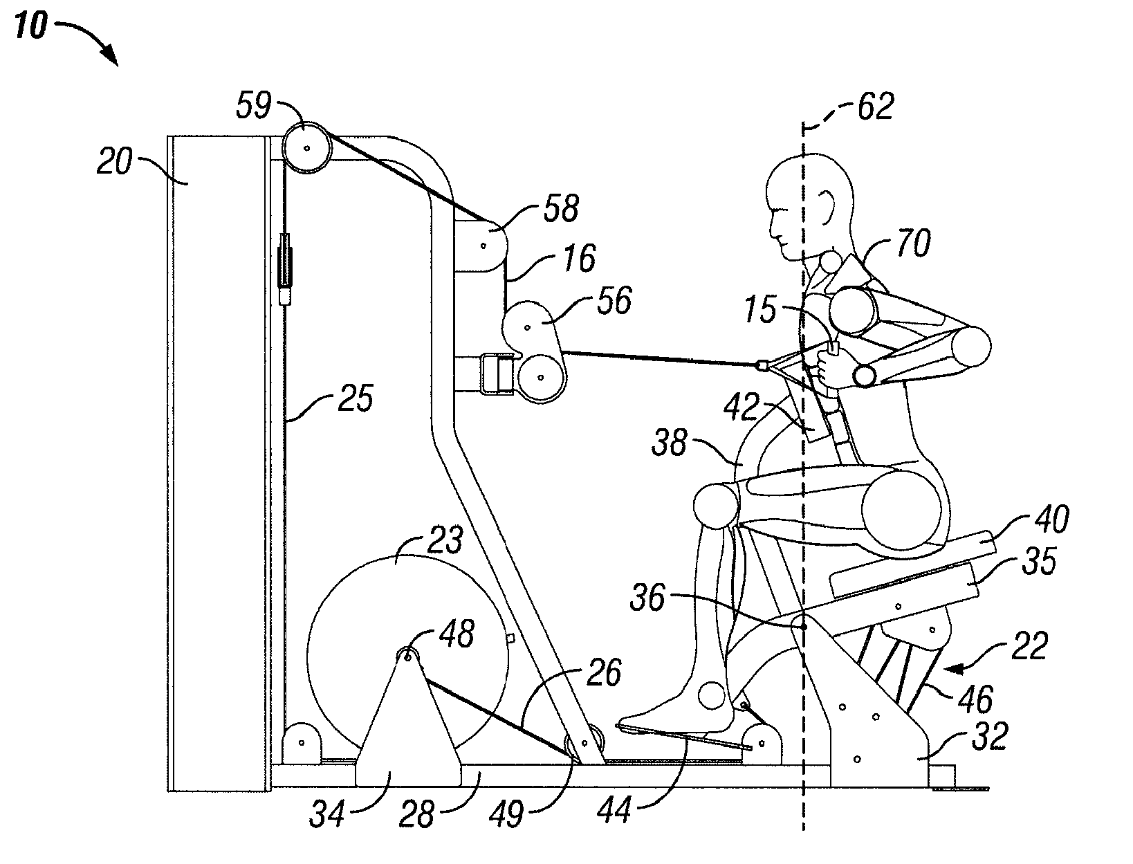
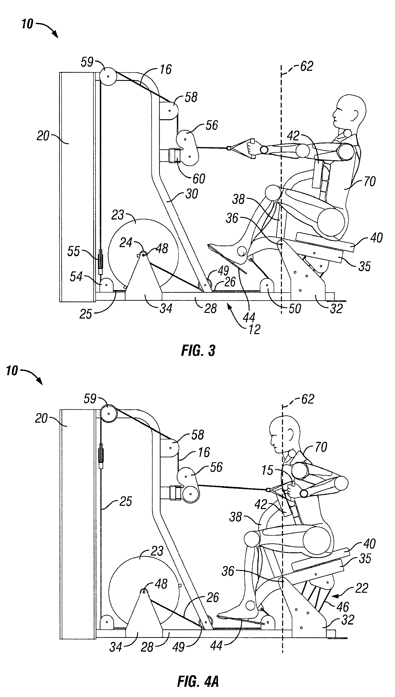
[0018]The pivot mounting of the user support defines a vertical gravitational center line of the pivotal movement, and in one embodiment portions of the combined weight of the user and user support frame are positioned on both sides of the vertical gravitational center line in at least one of the start and end positions of the exercise. In one embodiment, a portion of the combined weight of the user and user support is positioned on the movement side (i.e. the side the user support is pivoting towards) of the gravitational center line in the start position. This reduces the initial lifting resistance. By finishing the exercise with a portion of the combined user and user support weight on the trailing side of the center line in the movement direction, resistance “drop-off” at the end of an exercise is reduced. This distribution reduces the effect of the user's body weight on the resistance felt during the exercise. This is the opposite of most exercise devices that have moving user supports, which tend to rely on the weight of the user for resistance. Whether it is the starting or the finishing position, most prior art pivoting user supports place the majority of the user's weight on one or the other side of the gravitational center line of the pivoting movement, resulting in either a high initial lifting resistance, or else a resistance “drop off” at the end of the exercise.

Problems solved by technology

This design puts all of the user's weight on one side of the pivot, producing a high initial lifting resistance when the user starts the exercise, and also has no means for properly aligning the exercise arm and user support during the exercise movement.
Neither of these machines has any capability for aligning the user and user support with a rigid exercise arm, and thus do not maintain or support the user in the proper position throughout the exercise.
The user cannot truly isolate any one specific muscle or muscle group.
Because of this the user cannot fully fatigue other muscles as the abdominals and low back would fatigue first.
This reduces the initial lifting resistance.

Method used


Image

  • Exercise machine with multi-function user engagement device
  • Exercise machine with multi-function user engagement device
  • Exercise machine with multi-function user engagement device

Examples


second embodiment

[0106]FIGS. 9 to 16 illustrate an exercise machine 75 with a pivoting user support 76 which supports a user in an exercise position, and multi-function exercise arms 78 which have two modes of operation to perform either a shoulder press exercise which exercises the shoulder muscles, or a lat pulldown exercise which exercises the lat muscles of the back.

[0107]Exercise machine 75 has a stationary main frame 80 on which the user support 76 is pivotally mounted, and the exercise arms 78 are pivotally mounted on opposite sides of a rear upright portion 84 of the main frame to extend on opposite sides of the user support. A multiple part connecting linkage 86 is provided between the exercise arms 78 and the user support 76 so that movement of the exercise arms is translated into movement of the user support. Exercise resistance is provided by a bi-directional hydraulic ram assembly 88 which is pivotally secured to the upper end of main frame upright portion 84 at one end, and to the conn...

first embodiment

[0207]In each machine, the connecting linkage which translates the user engagement device movement into movement of the user support is associated with at least two of the user engagement device, user support, and main frame. In some embodiments, such as FIGS. 1 to 8, the connecting linkage is associated with all three of the user engagement device, user support, and main frame. The connecting linkage may have multiple parts or comprise a single rigid link, articulated links, completely flexible links, a roller on one part in rolling engagement with another part, and the like, and the connecting linkage may be made adjustable.

[0208]The exercise arm or user engagement device could be unidirectional or bi-directional, and may be in one piece (dependent) or two pieces for independent arm movement. The exercise arm may be mounted on the user support, main frame, or connecting linkage, and the exercise arm movement may be rotational, linear, converging, or diverging, and may be user-defi...


PUM


Abstract

An exercise machine has a main frame and a user support movably mounted relative to the main frame for movement between a start position and an end position during an exercise. At least one multi-function user engagement device is movably mounted relative to the frames for engagement and actuation by a user during an exercise, and a connecting linkage translates movement of the user engagement device to movement of the user support. The user engagement device has two different modes of operation selectable by a user for performing different exercises which exercise distinct muscles or muscle groups. A load provides resistance for both exercises.

Description

RELATED APPLICATION[0001]The present application is a Continuation-In-Part of co-pending U.S. patent application Ser. No. 10 / 633,805 filed on Aug. 4, 2003, and is also a Continuation-In-Part of co-pending U.S. patent application Ser. No. 11 / 846,472 filed on Aug. 28, 2007, and is also a Continuation-In-Part of co-pending U.S. patent application Ser. No. 11 / 848,012 filed on Aug. 30, 2007, and the contents of each of the aforementioned co-pending applications are incorporated herein by reference in their entirety. This application also claims priority to provisional application No. 61 / 059,035, filed Jun. 5, 2008, and the contents of the aforementioned provisional application are also incorporated herein by reference in their entirety.BACKGROUND[0002]1. Field of the Invention[0003]This invention relates generally to exercise machines with moving user supports, and is particularly concerned with an exercise machine which has a multi-function user engagement device.[0004]2. Related Art[00...

Claims


Application Information

Patent Timeline
IPC IPC(8): A63B21/00
CPCA63B21/0615A63B21/062A63B21/1484A63B21/1492A63B21/159A63B23/1245A63B23/1254A63B23/1263A63B21/068A63B22/0002A63B22/0089A63B22/203A63B23/0405A63B23/1281A63B2022/0005A63B2022/0079A63B2208/0233A63B2208/0247A63B21/0628A63B21/4043A63B22/0005A63B21/4047A63B23/1209A63B23/03525A63B23/1236A63B23/03566A63B21/4035A63B21/4031
Inventor WEBBER, RANDALL T.HOCKRIDGE, BRUCEMEREDITH, JEFFREY O.
Owner HOIST FITNESS SYST
Learn More