Eureka AIR delivers breakthrough ideas for toughest innovation challenges, trusted by R&D personnel around the world.

Rowing exercise machine with self-aligning pivoting user support

a user support and exercise machine technology, applied in the field of exercise machines, can solve the problems of increasing stress on the joints, difficult exercise for many people to perform using free weights, and increasing the difficulty of exercise, so as to reduce the effect of user's body weight on the resistance felt, reducing the initial lifting resistance, and reducing the resistance drop-off at the end of exercis

Active Publication Date: 2008-09-04
HOIST FITNESS SYST
View PDF99 Cites 42 Cited by
  • Summary
  • Abstract
  • Description
  • Claims
  • Application Information

AI Technical Summary

Benefits of technology

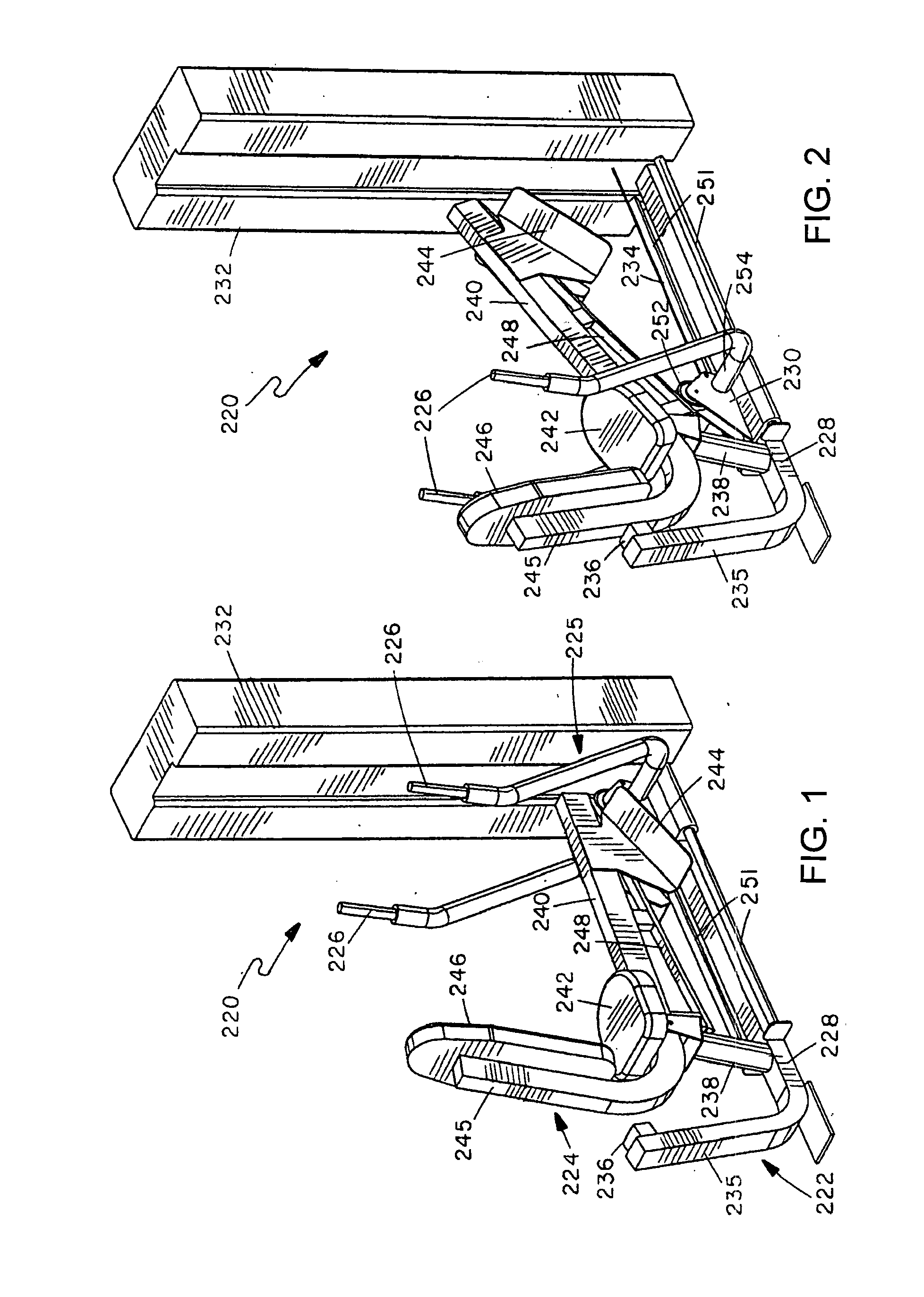
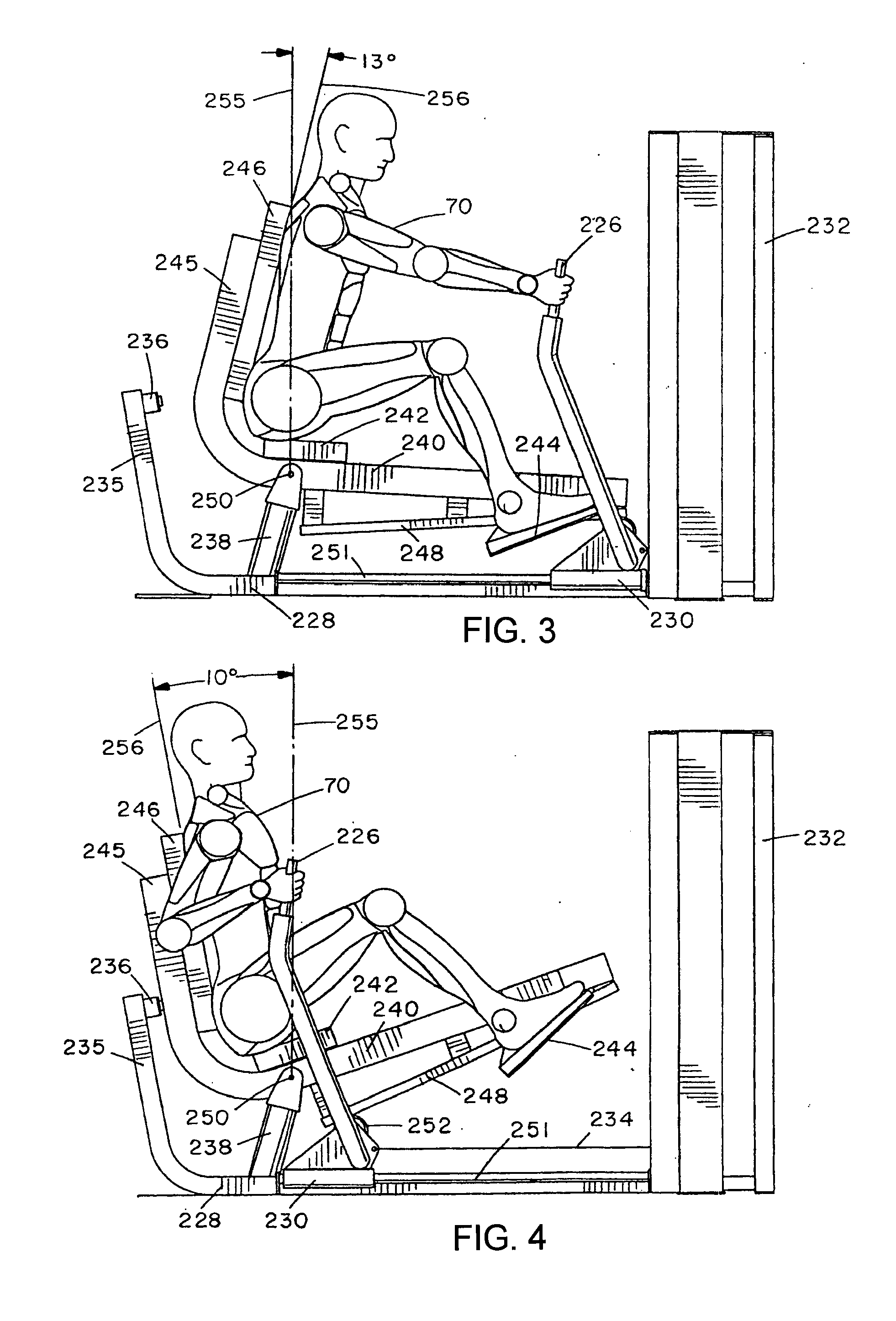
[0014]The user support frame in an exemplary embodiment has both a primary user support, such as a seat pad or back pad, and a secondary user support, such as a back pad, shoulder pad, thigh hold-down pads, chest pad, or the like. It may also have a supplementary stabilization means such as a foot rest, which may be mounted on, and travel with, the user support frame. Alternatively, a foot rest may be mounted on the main frame. In either case, the foot rest provides additional stabilization to the user, helping them to maintain a proper exercise position and providing additional comfort and support. The use of multiple support pads on the user support frame helps to position the exerciser properly and safely. These supports are in fixed alignment to each other and travel together, keeping the user in the same braced position throughout the entire exercise range of motion. This allows the user to focus on the exercise rather than worrying about their positioning on a moving platform or seat.
[0017]A pivot assembly which pivotally supports the user support frame may be located beneath the frame. The connecting linkage may be rigid, flexible, or partially flexible, and may be adjustable in length or position. The user engagement device or exercise arm may have one or two handles. If handles are provided, they may be rigid or flexible, fixed or self-aligning, and may provide two dimensional or three dimensional hand movement.
[0020]The pivot mounting of the user support defines a vertical gravitational center line of the pivotal movement, and in one embodiment portions of the combined weight of the user and user support frame are positioned on both sides of the vertical gravitational center line in at least one of the start and end positions of the exercise. In one embodiment, a portion of the combined weight of the user and user support is positioned on the movement side (i.e. the side the user support is pivoting towards) of the gravitational center line in the start position. This reduces the initial lifting resistance. By finishing the exercise with a portion of the combined user and user support weight on the trailing side of the center line in the movement direction, resistance “drop-off” at the end of an exercise is reduced. This distribution reduces the effect of the user's body weight on the resistance felt during the exercise. This is the opposite of most exercise devices that have moving user supports, which tend to rely on the weight of the user for resistance. Whether it is the starting or the finishing position, most prior art pivoting user supports place the majority of the user's weight on one or the other side of the gravitational center line of the pivoting movement, resulting in either a high initial lifting resistance, or else a resistance “drop off” at the end of the exercise.

Problems solved by technology

These exercises can be difficult for many people to perform using free weights, requiring balance and coordination as well as strength to follow the proper movement path.
Free rowing exercises often require an exerciser to bend at the waist, which is undesirable.
Improper form by the exerciser can make the exercise more difficult, increase stress on the joints, and even lead to possible injury.
One problem in most or all prior art designs is the unnatural and exaggerated arcing movement found in pivoting arm exercise machines, which do not accurately simulate the natural body movement found in free weight and / or free bar exercises.
This design puts all of the user's weight on one side of the pivot, producing a high initial lifting resistance when the user starts the exercise, and also has no means for properly aligning the exercise arm and user support during the exercise movement.
Neither of these machines has any capability for aligning the user and user support with a rigid exercise arm, and thus do not maintain or support the user in the proper position throughout the exercise.
Current exercise machines with pivoting or movable user supports often do not accurately maintain proper positioning of the user throughout the exercise motion, can result in awkward hand or wrist positions, and often involve exaggerated and unnatural arcing movements, or linear, non-arcing arm movements, rather than the smaller elliptical movement associated with free weight or natural exercise movements.
Often, an awkward starting or finishing position is required, potentially causing strain or injury.
The movement mimics the slight, naturally arcing movement of the upper body when rowing without any bending at the waist, which is undesirable and can occur with a free rowing exercise.
This reduces the initial lifting resistance.

Method used


Image

  • Rowing exercise machine with self-aligning pivoting user support
  • Rowing exercise machine with self-aligning pivoting user support
  • Rowing exercise machine with self-aligning pivoting user support

Examples


third embodiment

[0052]FIGS. 7 to 9 illustrate a rowing or mid-row exercise machine 350 comprising a main frame having a base 352, a user support frame 354 pivotally mounted on the main frame base 352 via a four bar pivot system 355, and a user engagement device or exercise arm 356 pivotally mounted on the main frame base 352 for rotation about pivot axis 358. Movement of the user engagement device 356 is translated into movement of the user support via a connecting linkage which in this case comprises a connecting link 360 pivoted between the user engagement device or exercise arm 356 and one of the links of the four bar pivot system 354, as explained in more detail below. User engagement device or exercise arm 356 is linked to a user selected amount of weight in a weight stack (not illustrated) in weight stack housing 362 at the forward end of the main frame, via a load bearing cable 364 extending from arm 356 between dual pulleys 365 at the base of the frame and then forward to the weight stack....

first embodiment

[0056]The user engagement device 356 may comprise separate, independently movable exercise arms or a U-shaped exercise arm as in the first embodiment which is pivoted to the main frame at the base of the U-shape for rotation about pivot axis 358. Handles or grips 391 are provided at the upper end of each exercise arm or upright exercise arm portion.

[0057]As noted above, FIG. 7 illustrates a user seated on the machine 350 in the start position for a mid-row exercise, while FIG. 8 illustrates the user and machine in the end position of the exercise. In order to perform a mid-row exercise, the user sits on user support seat 368 with their back against back pad 374, and reaches forward to grab the handles 391 of the user engagement device or exercise arms 356. This is the position illustrated in FIG. 7. The user then pulls the handles 391 inward towards their chest, stopping when the handles reach the end position of FIG. 8, just in front of their chest and slightly below shoulder level...


PUM


Abstract

A rowing or mid-row exercise machine has a main frame and a user support frame pivotally mounted relative to the main frame for rotation between start and end positions. The user support frame supports spaced positions on a user's body in the same relative orientation throughout an exercise movement. A user engagement device is movably mounted relative to the frames and has at least one handle gripped by the user in performing exercises. The handle is movable in a predetermined rowing exercise path between a start position spaced in front of a user's chest and an end position closer to the chest. A connecting linkage translates movement of the user engagement device to rotational movement of the user support frame. A load resists movement of at least one of the user support, user engagement device, and connecting linkage.

Description

RELATED APPLICATION[0001]The present application is a Continuation-In-Part of co-pending U.S. patent application Ser. No. 10 / 633,805 filed on Aug. 4, 2003, the contents of which are incorporated herein by reference in their entirety.BACKGROUND[0002]1. Field of the Invention[0003]This invention relates generally to exercise machines, and is particularly concerned with a rowing exercise machine with a pivoting user support.[0004]2. Related Art[0005]There are several different types of exercise for exercising back muscles, including mid-row exercises. These exercises can be difficult for many people to perform using free weights, requiring balance and coordination as well as strength to follow the proper movement path. Free rowing exercises often require an exerciser to bend at the waist, which is undesirable. Improper form by the exerciser can make the exercise more difficult, increase stress on the joints, and even lead to possible injury.[0006]Various exercise machines have been dev...

Claims


Application Information

Patent Timeline
Patent Type & Authority Applications(United States)
IPC IPC(8): A63B69/06
CPCA63B21/0615A63B21/062A63B21/068A63B21/1469A63B21/1488A63B21/1492A63B2022/0079A63B22/0002A63B22/0056A63B22/0089A63B22/203A63B23/03525A63B21/159A63B21/0628A63B21/4035A63B21/4045A63B21/4047
Inventor WEBBER, RANDALL T.HOCKRIDGE, BRUCEMEREDITH, JEFFREY O.
Owner HOIST FITNESS SYST
Why Eureka
Eureka Blog
Learn More