
Thermal barrier fabric

a fabric and thermal barrier technology, applied in the direction of synthetic resin layered products, protective garments, packaging, etc., can solve the problems of garments that are difficult to work, garments are typically extremely bulky and heavy, and neither of the above approaches is suitable for cold water exposur

Inactive Publication Date: 2011-07-12
ARMY USA AS REPRESENTED BY THE SEC OF THE
View PDF13 Cites 10 Cited by
  • Summary
  • Abstract
  • Description
  • Claims
  • Application Information

AI Technical Summary

Benefits of technology

"The invention provides a lightweight, non-bulky material for thermally protective garments that can be worn in water without restricting the wearer's freedom of movement. The material has a reflective layer that reflects body heat back towards the wearer and a vacuum that prevents heat transfer through the material. The invention also provides a heat barrier material for enclosures that provides thermal shielding of the contents. The material is constructed with an inner and outer impermeable material layer, a spacer material, and a reflective layer of material that is bound together to create a closed compartment that is under a vacuum. The reflective layer reflects thermal energy back towards a source of heat and the vacuum prevents heat transfer through the material. The invention can be applied in various embodiments without limiting the scope of the invention."

Problems solved by technology

Such garments typically are extremely bulky and heavy.
While providing protection from the elements, such garments are difficult to work in because of the bulkiness of the garment.
Neither of the above approaches is suitable for cold water exposure.

Method used


Image

  • Thermal barrier fabric
  • Thermal barrier fabric
  • Thermal barrier fabric

Examples


Embodiment Construction

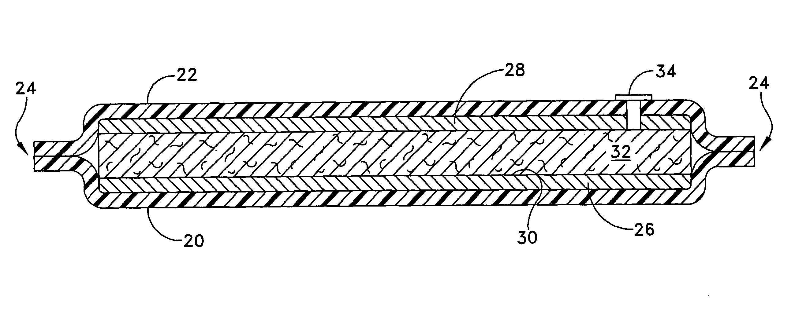
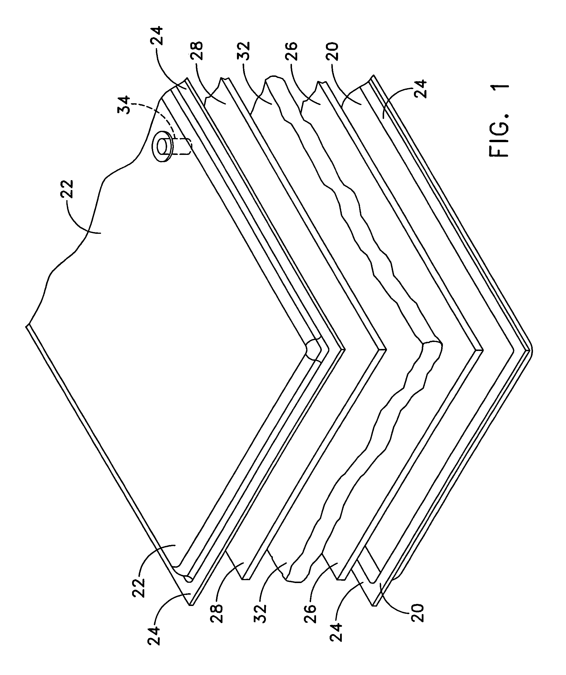
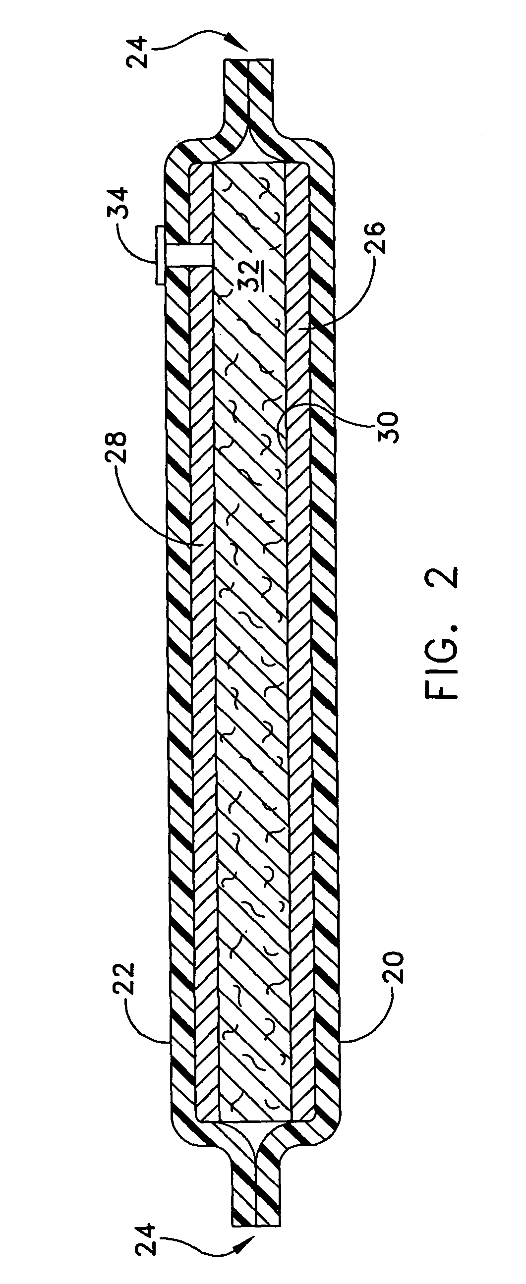
[0022]Referring to the drawings, it will be seen that an illustrative fabric for conservation of body heat of a wearer includes an inner impermeable material layer 20 and an outer impermeable material layer 22. The inner and outer material layers 20, 22 are preferably of a polymer material, a fusible silicon, or other impermeable material coated with an adhesive in the areas 24 in which the inner and outer material layers are joined to each other. Alternatively, the inner and outer layers 20, 22 may be of a woven, knit or non-woven cloth material coated with a polymer material or a fusible silicone to render the inner and outer layers impermeable.

[0023]The inner and outer layers 20, 22 are bound to each other in a stitchless manner in the areas 24, as by fusion, heat sealing, ultrasonic sealing, laser sealing, adhesive sealing, or the like. The cloth inner and outer layers 20, 22 are preferred for non-water environments.

[0024]Adjacent at least one of the impermeable material layers ...


PUM

PropertyMeasurementUnit
thicknessaaaaaaaaaa
impermeableaaaaaaaaaa
volumeaaaaaaaaaa

Abstract

A thermal barrier fabric includes an inner impermeable material layer, an outer impermeable material layer, a spacer material disposed between the inner and outer impermeable material layers, and a reflective layer of material disposed between the spacer and a selected one of the inner impermeable material layer and the outer impermeable material layer. The inner and outer impermeable material layers are bound to each other along portions thereof outboard of the spacer material and the reflective layer of material to define a closed compartment. The compartment is under a vacuum, such that the reflective layer of the fabric reflects thermal energy back toward the source thereof and the vacuum substantially prevents thermal energy transfer through the compartment.

Description

STATEMENT OF GOVERNMENT INTEREST[0001]The invention described herein may be manufactured and used by the U.S. Government for Governmental purposes without the payment of any royalty thereon.BACKGROUND OF THE INVENTION[0002]1. Field of the Invention[0003]The invention relates to fabric for use as a thermal barrier, as in protective clothing, and is directed more particularly to fabric for garments for conserving body heat of a wearer exposed to a cold environment, such as frigid air or water, or for protecting a wearer against exposure to severe heat or cold, and for use in other enclosures requiring thermal obstruction.[0004]2. Description of the Prior Art[0005]It is known to provide garments for the protection of wearers against elements which can be injurious to the wearer's well-being. One approach is to use materials which are of a thickness providing protection to the wearer against cold air. Such garments typically are extremely bulky and heavy. While providing protection from...

Claims


Application Information

Patent Timeline
Patent Type & Authority Patents(United States)
IPC IPC(8): B32B5/26B32B27/04
CPCA41D31/0038B32B5/18B32B5/26B32B15/14B32B5/24Y10T428/2495B32B5/022B32B5/024B32B5/026B32B5/22B32B5/245B32B7/14B32B15/046B32B15/08B32B27/065B32B27/08B32B27/12B32B27/283B32B27/36B32B3/04B32B3/08B32B3/266B32B2255/02B32B2255/10B32B2255/26B32B2262/0253B32B2262/0269B32B2307/304B32B2307/50B32B2307/518B32B2307/546B32B2307/718B32B2307/7265B32B2437/00B32B2439/70B32B2471/04B32B2571/00A41D31/065Y10T442/647Y10T442/223Y10T442/2598Y10T442/659Y10T442/656Y10T442/69Y10T428/249981
Inventor SZCZESUIL, STEPHEN P.
Owner ARMY USA AS REPRESENTED BY THE SEC OF THE
Learn More