Closure having RFID and foil

a technology of foil and lid, applied in the field of packaging, can solve the problems of rfid performance, problems encountered, and rfid damage,

Inactive Publication Date: 2011-07-05
BPREX HEALTHCARE PACKAGING INC
View PDF77 Cites 47 Cited by
  • Summary
  • Abstract
  • Description
  • Claims
  • Application Information

AI Technical Summary

Benefits of technology

[0008]According to the present invention a closure having an RFID and induction foil for induction heat sealing at least one component part of the closure and / or the closure to a container wherein the induction foil is of a metallic material and the sealing is brought about through the inducement of a magnetic field in the metallic induction foil by a radio frequency coil. The closure with the RFID and induction foil is exposed to a radio frequency current causing a magnetic field to be induced in the induction foil which causes the temperature of the foil to increase which melts thermoplastic material proximate the induction foil to a softened or melted state and thus brings about adhesion or bonding between the proximate thermoplastic materials and foil.

Problems solved by technology

However, a problem existing with many applications of RFIDs in closures is that the RFID can be damaged during the production of a closure having an RFID or when sealing the closure having the RFID to a container.
Other problems have been found with the performance of the RFID when metals are incorporated into a closure or closure and container combination.
Problems have been encountered with use of RFIDs with containers and closures having induction foil incorporated therein.
The heat generated during the induction process can render an RFID device inoperable thus restricting or even prohibiting the use of an RFID device when using an induction sealing process with a closure or closure and container combination.
Additionally, radio waves bounce off metal causing interference from the metal disrupting the RFID signal.
Moreover, metal causes eddy currents in the vicinity of the RFID reader antennae which absorb RF energy, thus reducing the overall effectiveness of the RFID field.
Furthermore, metal can also detune both reader and tag antenna, causing added parasitic capacitance reducing system performance.
Finally, at some frequencies the energy reflected by metal creates interference between the tag and reader.

Method used


Image

  • Closure having RFID and foil
  • Closure having RFID and foil
  • Closure having RFID and foil

Examples


Embodiment Construction

[0014]The following detailed description is given primarily for clearness of understanding and no unnecessary limitations are to be understood there from and modifications will become obvious to those skilled in the art upon reading the disclosure and may be made without departing from the spirit of the invention and scope of the appended claims.

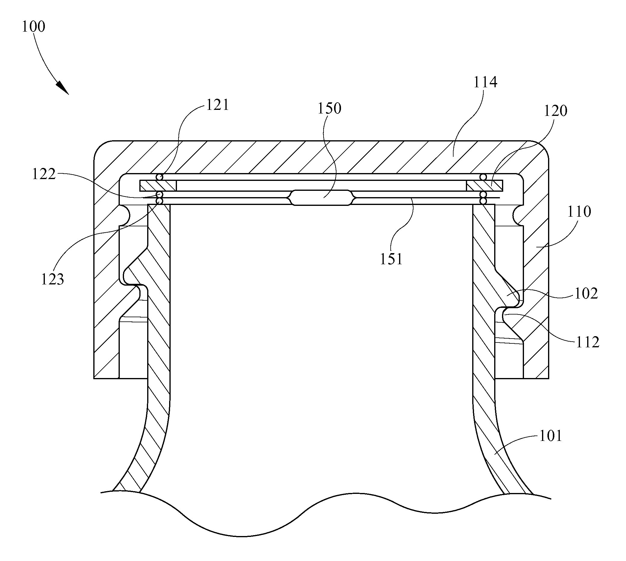
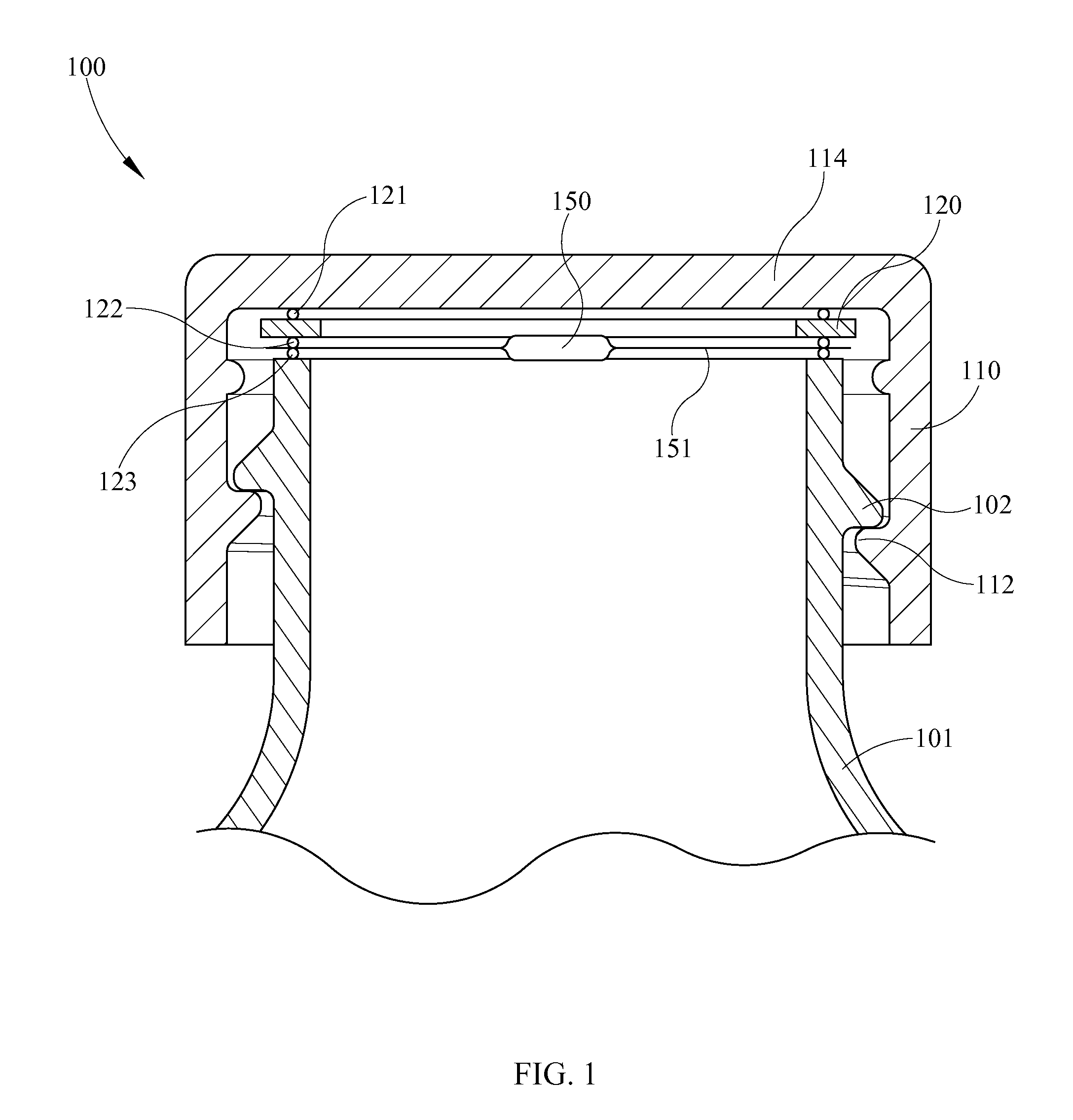
[0015]FIG. 1 shows closure 100 and container 101 wherein closure 100 has RFID 150 contained within film 151. Closure 100 is a screw type closure having top wall 114 with annular depending side wall 110. Side wall 110 has helical thread 112 depending from an inner annular surface thereof for engaging helical thread 102 on the neck of container 101. RFID 150 is disposed proximate top wall 114 within film 151 which is inductively sealed to closure 100 and container 101. Top wall 114 has annular side wall 110 depending there from. Induction foil 120 is circular with a hollow center or a ring configuration and is adjacent an inner surface of top ...


PUM

PropertyMeasurementUnit
Radiusaaaaaaaaaa
Distanceaaaaaaaaaa
Metallic bondaaaaaaaaaa

Abstract

A closure comprising a top wall with an annular side wall depending there from. An induction foil is proximate an inner surface of the top wall and may have a ring or circular configuration. An RFID device is affixed or is integral with the closure a minimum distance from and / or orientation with the induction foil as to prevent damage to the RFID device during an induction sealing process and to reduce adverse operational effects of the RFID from the foil. The RFID may be active or passive and may be proximate or integral with the top wall or integral with the side wall of the closure. The RFID may be contained within a film wherein a portion of the film is inductively sealed to the closure.

Description

CROSS-REFERENCE TO RELATED APPLICATIONS[0001]Not applicable.STATEMENT REGARDING FEDERALLY SPONSORED RESEARCH OR DEVELOPMENT[0002]Not applicable.FIELD OF INVENTION[0003]The present invention generally relates to packaging having a radio frequency identification (RFID) therein for relaying information regarding the packaging and / or contents thereof. More specifically, the present invention relates to closures for containers having an RFID.BACKGROUND OF THE INVENTION[0004]The development of integrated circuitry, particularly RFIDs, has permitted use of such devices in a wide range of applications. RFIDs first appeared in tracking and access applications during the 1980s. These wireless systems allow for non-contact reading and are effective in manufacturing and other hostile environments where bar code labels could not survive. RFID has established itself in a wide range of markets including livestock identification and automated sorting systems because of its ability to track moving o...

Claims


Application Information

Patent Timeline
IPC IPC(8): G08B13/14G06F19/00G08B1/08H01L21/00G06K19/00
CPCB29C65/3644B29C66/112B29C66/114B29C66/534B29C66/53461B29C66/541B29C66/542B65D51/20G06K19/041G06K19/07771G06K19/07798B29C65/4815B29C65/76B29L2031/565B65D2203/10H01L21/67294B29C65/3676B29C65/5057
Inventor LAMBERT, PHILBRANSON, MARKSHANKLAND, WILLIAM
Owner BPREX HEALTHCARE PACKAGING INC
Why Eureka
Try Eureka