
Carbon nanotube-conductive polymer composite

a technology of conductive polymer and carbon nanotube, which is applied in the direction of non-metal conductors, cell components, conductors, etc., can solve the problems of reducing the resistance cnts cannot form a good electric conductive network, and the performance of the carbon nanotube-conductive polymer composite is negatively affected

Active Publication Date: 2011-07-05
TSINGHUA UNIV +1
View PDF26 Cites 18 Cited by
  • Summary
  • Abstract
  • Description
  • Claims
  • Application Information

AI Technical Summary

Benefits of technology

[0006]The conventional carbon nanotube-conductive polymer composite includes a plurality of CNTs with conductive polymer pellets distributed in the gaps among the CNTs. The carbon nanotube-conductive polymer composite is applicable in the field of super capacitors, in solar cell electrodes, in which charging and discharging of the conductive polymer pellets contract and expand conductive polymer pellet volume. The spatial structures of CNTs may alleviate the volume contraction and expansion of the carbon nanotube-conductive polymer composite caused by the mentioned volume contraction and expansion of the conductive polymer pellet. Moreover, the carbon nanotube-conductive polymer composite's high electrical conductivity may reduce the resistance of the carbon nanotube-conductive polymer composite. Therefore, the carbon nanotube-conductive polymer composite provides favorable electrical conductivity and high specific electric capacity (exceeding 200 Farad / grams). However, in conventional technology, CNTs of the carbon nanotube-conductive polymer composite require dispersal in strong oxidized acid, such as sulfuric or nitric acid and surfactant, followed by electrochemical reaction with the conductive polymer pellets, with the result that carbon nanotube-conductive polymer composite film is finally obtained on the working electrode. Using the strong acid solution to disperse the CNTs destroys the CNTs. Additionally, since the surfactant is not easily removed from the carbon nanotube-conductive polymer composite, performance of the carbon nanotube-conductive polymer composite is negatively affected. Moreover, because CNTs are easy to reunite, in the conventional technology, the CNTs cannot form a good electric conductive network. Considerable spacing between adjacent CNTs increases resistance of the carbon nanotube-conductive polymer composite and decreases specific electric capacity thereof, adversely affecting electrical conductivity and heat conduction of the CNTs be fully performed.

Problems solved by technology

Moreover, the carbon nanotube-conductive polymer composite's high electrical conductivity may reduce the resistance of the carbon nanotube-conductive polymer composite.
Additionally, since the surfactant is not easily removed from the carbon nanotube-conductive polymer composite, performance of the carbon nanotube-conductive polymer composite is negatively affected.
Moreover, because CNTs are easy to reunite, in the conventional technology, the CNTs cannot form a good electric conductive network.
Considerable spacing between adjacent CNTs increases resistance of the carbon nanotube-conductive polymer composite and decreases specific electric capacity thereof, adversely affecting electrical conductivity and heat conduction of the CNTs be fully performed.

Method used


Image

  • Carbon nanotube-conductive polymer composite
  • Carbon nanotube-conductive polymer composite
  • Carbon nanotube-conductive polymer composite

Examples


Embodiment Construction

[0017]Reference will now be made to the drawings to describe various embodiments of the present carbon nanotube-conductive polymer composite, in detail.

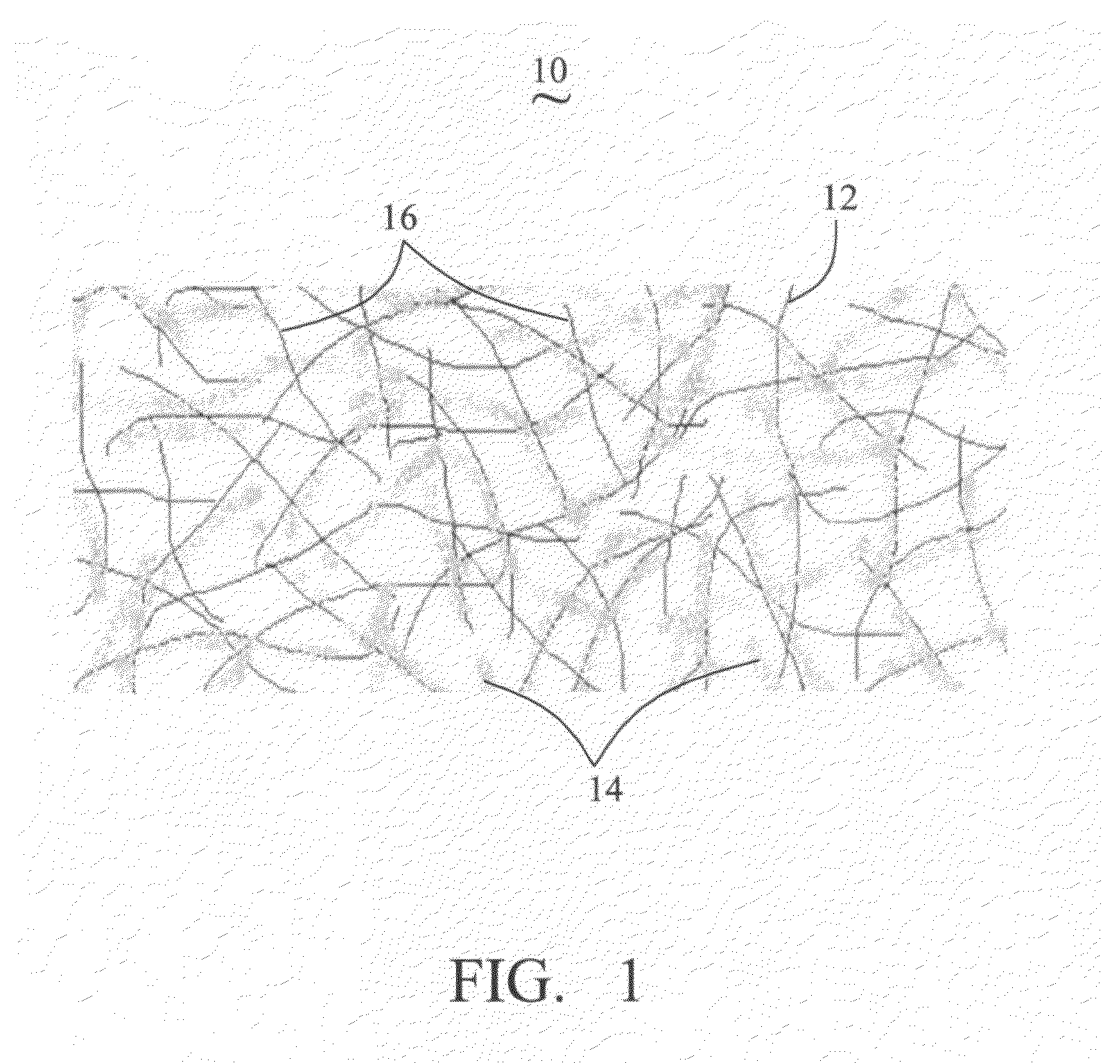
[0018]Referring to FIG. 1, a carbon nanotube-conductive polymer composite 10 includes a number of CNTs 12 and conductive polymer fibers 14. The CNTs are connected with each other to form a carbon nanotube network 16. The conductive polymer fibers 14 adhere to surfaces of the CNTs. The carbon nanotube network 16 forms a skeleton to which the conductive polymer fibers 14 adhere. The CNTs 12 and conductive polymer fibers 14 are uniformly distributed in the carbon nanotube-conductive polymer composite 10.

[0019]In the present embodiment, the CNTs 12 of the carbon nanotube network 16 are disordered or in isotropic arrangement. The disordered CNTs 12 are attracted and packed together closely by van Der Waals force, attaching to one another to form a uniformly distributed structure. The isotropic CNTs 12 are attracted by van Der Waals force ...


PUM

PropertyMeasurementUnit
diametersaaaaaaaaaa
diametersaaaaaaaaaa
diameteraaaaaaaaaa

Abstract

A carbon nanotube-conductive polymer composite includes a plurality of CNTs and conductive polymer fibers. The CNTs are connected with each other to form a network. The conductive polymer fibers adhere to surfaces of the CNTs and / or tube walls of the CNTs.

Description

RELATED APPLICATIONS[0001]This application is related to commonly-assigned applications: U.S. patent application Ser. No. 12 / 487,284, entitled, “METHOD FOR MAKING CARBON NANOTUBE-CONDUCTIVE POLYMER COMPOSITE”, filed Jun. 18, 2009; U.S. patent application Ser. No. 12 / 487,291, entitled “METHOD FOR MAKING A CARBON NANOTUBE-CONDUCTIVE POLYMER COMPOSITE”, filed Jun. 18, 2009. The disclosures of the above-identified applications are incorporated herein by reference.BACKGROUND[0002]1. Field of the Disclosure[0003]The disclosure relates to a carbon nanotube / polymer composite, and particularly to a carbon nanotube-conductive polymer composite.[0004]2. Description of Related Art[0005]Carbon nanotubes (CNTs) have a high Young's modulus, high thermal conductivity, and high electrical conductivity, among other properties, making them an ideal composite material supplement. It has thus been suggested that CNT composite materials can play an important role in fields such as microelectronics, mater...

Claims


Application Information

Patent Timeline
Patent Type & Authority Patents(United States)
IPC IPC(8): H01B1/04H01B1/12B82Y30/00B82Y99/00C01B31/02C08K3/04C08L101/12H01G11/22H01G11/30H01G11/36H01G11/48H01M4/36H01M4/583H01M4/60H01M4/86H01M14/00
CPCB82Y30/00B82Y40/00C01B31/0206H01M4/583C08J5/005H01B1/24C01B2202/02C01B2202/04C01B2202/08C01B2202/34C01B2202/36C01B2202/06C01B32/15Y02E60/10
Inventor MENG, CHUI-ZHOULIU, CHANG-HONGFAN, SHOU-SHAN
Owner TSINGHUA UNIV
Learn More