
Electronic device with an antitheft function and method for preventing theft of electronic devices

Inactive Publication Date: 2011-06-28
SANYO ELECTRIC CO LTD
View PDF4 Cites 2 Cited by
  • Summary
  • Abstract
  • Description
  • Claims
  • Application Information

AI Technical Summary

Benefits of technology

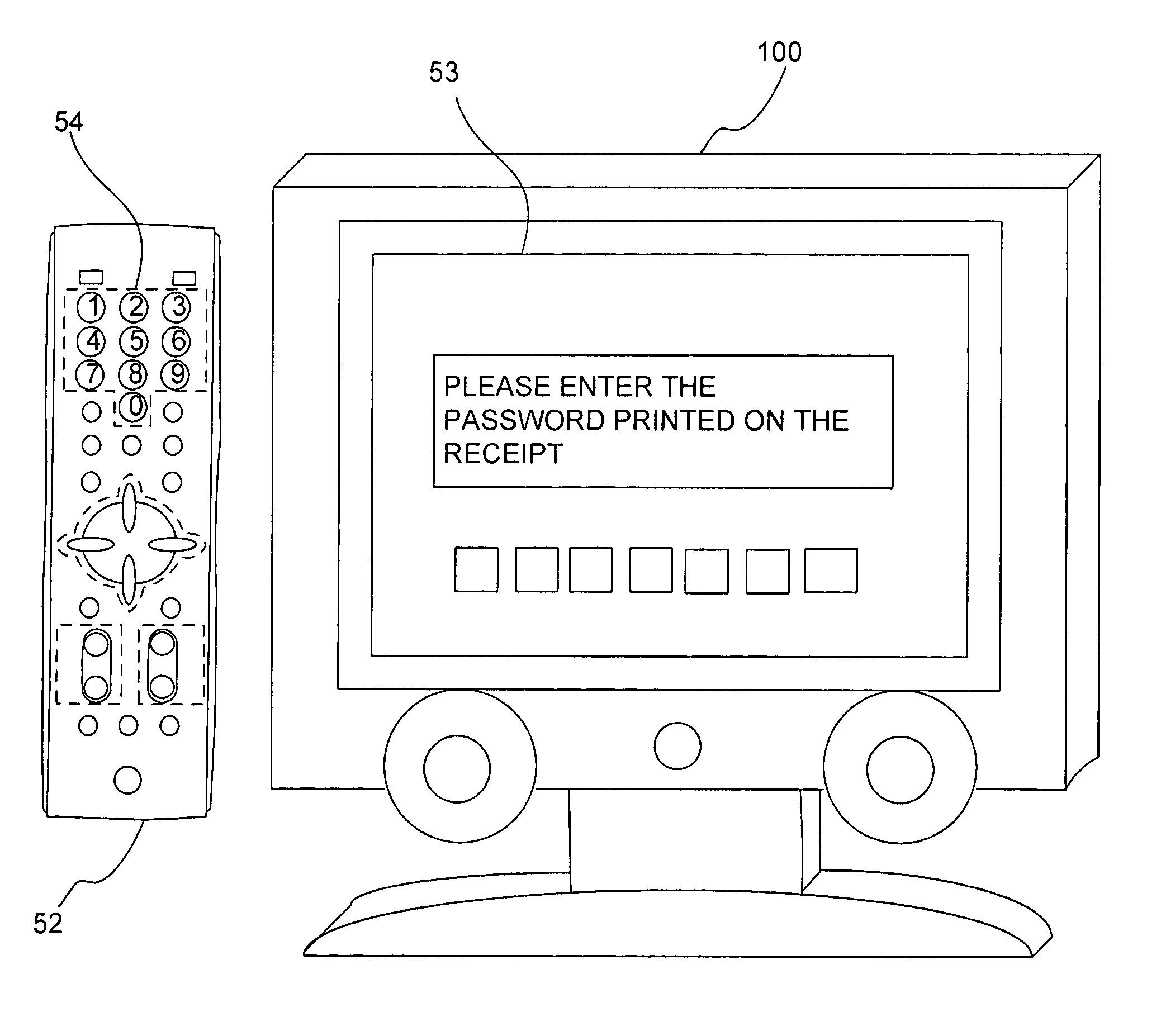
[0008]By configuring as described above, the television receiver does not operate when the result of the comparison is not confirmed. Therefore, by providing the second lock release code only to those who legitimately purchase the television receiver, those who did not legitimately purchase the television receiver (for example, a thief) can not use the television receiver because he or she does not know the second lock release code. Also, there is no value in reselling the television receiver because it can not be used. In this way, thieves are demotivated, and the damage of thefts are decreased.
[0035]By configuring as described above, the information can be read by the CCD camera, thus the input operation can be made easily without having to trouble an user compared to input using buttons and so on. Also, the camera will not operate by the number randomly input by a thief.

Problems solved by technology

Therefore, by providing the second lock release code only to those who legitimately purchase the television receiver, those who did not legitimately purchase the television receiver (for example, a thief) can not use the television receiver because he or she does not know the second lock release code.
Also, there is no value in reselling the television receiver because it can not be used.

Method used


Image

  • Electronic device with an antitheft function and method for preventing theft of electronic devices
  • Electronic device with an antitheft function and method for preventing theft of electronic devices
  • Electronic device with an antitheft function and method for preventing theft of electronic devices

Examples


Embodiment Construction

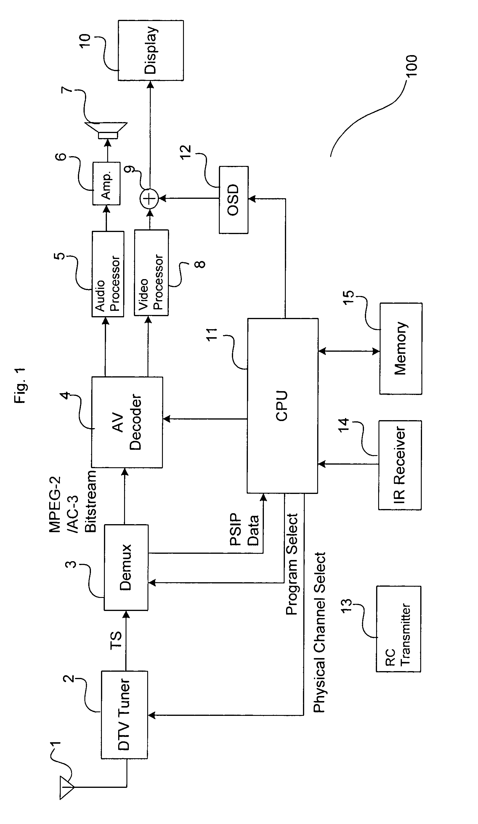
[0048]FIG. 1 shows a block diagram of a television receiver 100 according to the present invention. In this embodiment, an U.S. digital television receiver which receives an ATSC signal is described as an embodiment.

[0049]A terrestrial antenna 1 receives digital terrestrial broadcasting wave, and supplies a received signal to a digital terrestrial tuner 2. The tuner selects a physical channel by a channel select signal from a CPU or a microprocessor 11. The digital terrestrial tuner 2 retrieves a specific frequency signal from a high frequency digital modulation signal 8VSB (8-level vestigial sideband modulation) including video / audio data by this channel select process. Also, the digital terrestrial tuner 2 is provided with a 8VSB demodulation circuit and alike to demodulate the digital modulation signal of selected physical channel and outputs a transport stream TS.

[0050]A demultiplexer (DEMUR) 3 divides the transport stream TS received from the digital terrestrial tuner 2 into a ...


PUM


Abstract

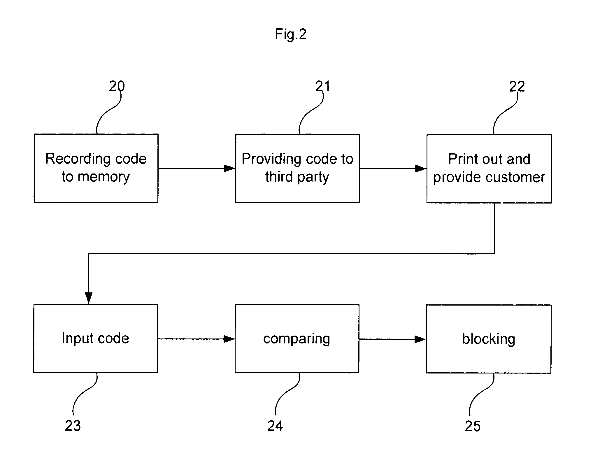
The present invention is a television receiver that includes a memory that stores a first lock release code, an input device to input a second lock release code, a comparing portion to compare the second lock release code to the first lock release code, and a control portion to output a signal to operate the television receiver when the result of the comparison conforms. Also the present invention includes a method for preventing theft of an electronic device that includes the steps of storing a lock release code in a memory of the electronic device, providing information corresponding to the lock release code to a third party, requesting an input of the information corresponding to the lock release code, comparing input information to the lock release code stored in the memory, and disabling the electronic device when the result of the comparison is not conforming.

Description

TECHNICAL FIELD[0001]The objective of present invention is to prevent theft of electronic devices from stores and so on. That is, in the present invention, the electronic device can not be used unless an input code corresponds to a predetermined code stored in a memory which is integrated in the electronic device.BACKGROUND OF INVENTION[0002]Conventionally, a typical method for preventing theft of electronic devices is to, for example, embed a sensor called sensor tag on a piece of merchandise or to attach the merchandise to a carton case, and install a sensor in the doorway of a store to detect and sound a buzzer when the merchandise is removed from a store without releasing the function of the sensor at a cash register. However, the effect raises a question because the sensor tag loses its effect once it is removed, and further the electronic devices are still stolen even when the buzzer goes off.[0003]And, Japanese published unexamined application No. 2007-81669 discloses a metho...

Claims


Application Information

Patent Timeline
IPC IPC(8): H04N7/16
CPCG06F21/88H04N21/4627H04N21/4753H04N21/4784G06F2221/2115G06F2221/2147H04W12/12G06F2221/2153H04W12/126
Inventor GAKUMURA, HIROKIBABA, HIDEKITSURUSAKI, AKIRA
Owner SANYO ELECTRIC CO LTD
Learn More