
Isolation and support structures for hydrogen hybrid locomotives and hydrogen hybrid locomotives using the same

Active Publication Date: 2011-06-28
BNSF RAILWAY
View PDF42 Cites 29 Cited by
  • Summary
  • Abstract
  • Description
  • Claims
  • Application Information

AI Technical Summary

Benefits of technology

[0009]The embodiments of the principles of the present invention address a number of technical problems related to weight, center of gravity, packaging, and safety, not found in the development of hydrogen hybrid fuel cell propulsion systems for smaller vehicles. As a result, a number of significant advantages can be realized as hydrogen hybrid fuel cell locomotives embodying the principles of the present invention are deployed. Among other things, such hydrogen hybrid fuel cell locomotives help reduce particulate air pollution in urban rail yards, as well as reduce the amount of greenhouse gases expelled into the atmosphere. Furthermore, the use of hydrogen as a fuel reduces the dependency of the railroads on imported oil and decouples locomotive operating costs from the volatile fossil fuel markets. Moreover, hydrogen hybrid fuel cell locomotives can act as mobile electricity sources, for example in disaster recovery scenarios.

Problems solved by technology

Yet, like many industries, the railroad industry is facing numerous challenges related to the upward trend in the cost of fossil fuels and increasing pressure to limit the impact of trains on the environment.
The root cause for many of these challenges is the propulsion systems traditionally used in railroad locomotives.
On the other hand, because diesel-electric locomotives consume diesel, they contribute to urban air pollution and are subject to operating costs tied directly to the cost of oil.
This large distributed power system is typically unsuitable for remove geographic regions and overall is less efficient than a system utilizing diesel locomotives.
However, any such alternative systems must be capable of meeting the rigors experienced by locomotives everyday, including the shock loads generated during the coupling of rail cars.

Method used


Image

  • Isolation and support structures for hydrogen hybrid locomotives and hydrogen hybrid locomotives using the same
  • Isolation and support structures for hydrogen hybrid locomotives and hydrogen hybrid locomotives using the same
  • Isolation and support structures for hydrogen hybrid locomotives and hydrogen hybrid locomotives using the same

Examples


Embodiment Construction

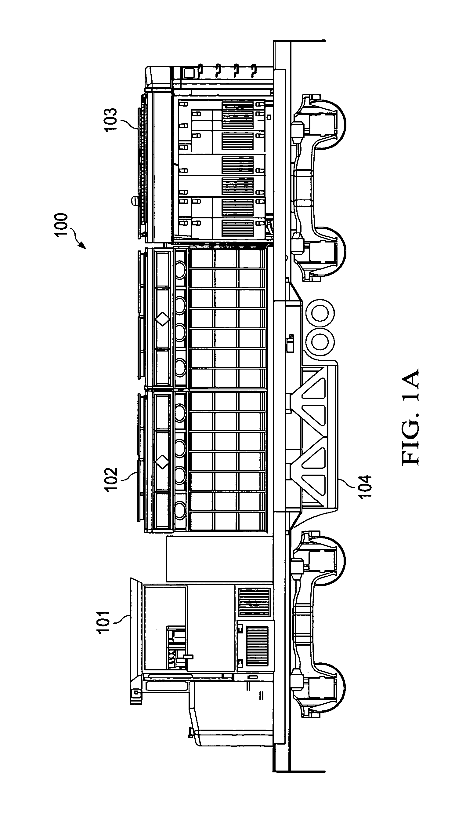
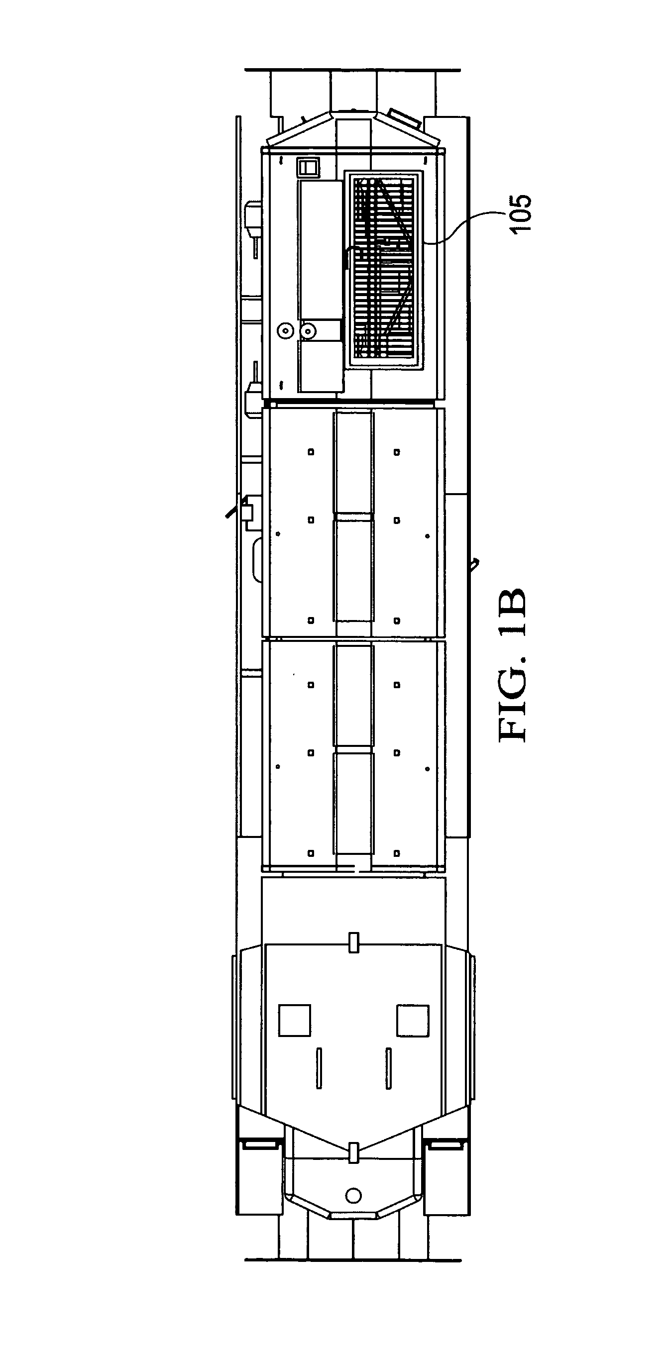
[0033]The principles of the present invention and their advantages are best understood by referring to the illustrated embodiment depicted in FIGS. 1-17 of the drawings, in which like numbers designate like parts.

[0034]FIGS. 1A-1D are respectively left-side, top, front, and rear views of a hydrogen fuel cell hybrid (“hydrogen hybrid”) switching locomotive 100 embodying the principles of the present invention. It should be recognized that while the principles of the present invention are being described with respect to a switching locomotive embodiment, these principles are applicable to the design and construction of line-haul locomotives, as well.

[0035]The various components and subsystems of hydrogen hybrid locomotive 100 will be discussed in detail below. Generally, hydrogen hybrid locomotive 100 includes a cab section 101 containing the control systems used by the operator, a center section 102 containing the batteries and the hydrogen storage tanks, a rear housing section 103 c...


PUM


Abstract

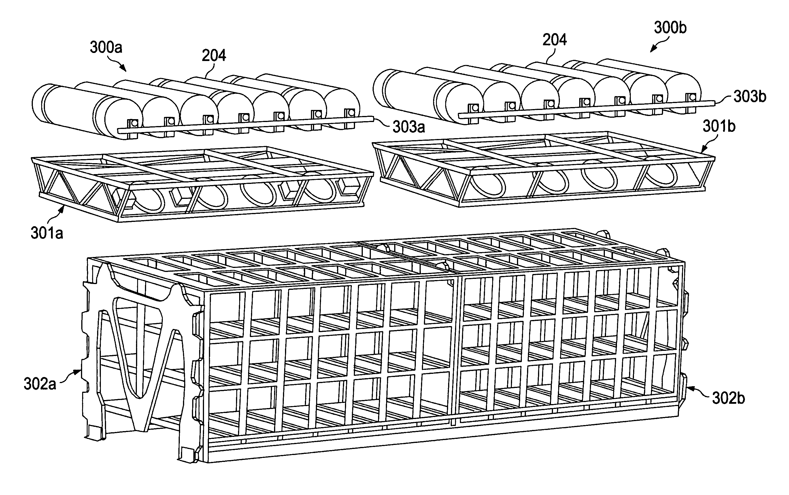
A hydrogen hybrid locomotive driven by a set of electric traction motors powered by at least one hydrogen fuel cell power module and plurality of batteries includes a chassis, an isolation structure disposed on the chassis for isolating the at least one hydrogen fuel cell power module from shock and vibration and a battery rack disposed on the chassis for supporting the plurality of batteries. A hydrogen containment module is disposed above the battery rack and includes a support rack supporting a plurality of hydrogen tanks and a manifold coupled to each of the plurality of hydrogen tanks for allowing charging and discharging of the hydrogen tanks.

Description

CROSS-REFERENCE TO RELATED APPLICATION[0001]The present application is a continuation of U.S. patent application Ser. No. 12 / 462,473, filed Aug. 4, 2009, to Miller et al. for “Hydrogen Fuel Cell Hybrid Locomotives” and claiming the benefit of U.S. Provisional Patent Application Ser. No. 61 / 137,950, filed Aug. 5, 2008.FIELD OF INVENTION[0002]The present invention relates in general to railroad locomotives, and in particular to, hydrogen fuel cell hybrid locomotives.BACKGROUND OF INVENTION[0003]Railroads remain one of the most efficient means for transporting freight and passengers over relatively long distances. Yet, like many industries, the railroad industry is facing numerous challenges related to the upward trend in the cost of fossil fuels and increasing pressure to limit the impact of trains on the environment. The root cause for many of these challenges is the propulsion systems traditionally used in railroad locomotives.[0004]Diesel-electric locomotives employ a diesel engine...

Claims


Application Information

Patent Timeline
IPC IPC(8): B61C3/00
CPCB61C7/04B60K6/32Y02T90/34Y02T30/16Y02T90/32H01M2250/20Y02T30/00Y02T90/40Y02E60/50
Inventor MILLER, ARNOLD R.HESS, KRIS S.ERICKSON, TIMOTHY L.DIPPO, JAMES L.
Owner BNSF RAILWAY
Learn More