Sealing element for a brake cylinder of a vehicle braking system

a technology for sealing elements and brake cylinders, which is applied in the direction of brake systems, couplings, mechanical devices, etc., can solve the problems that the sealing lip may no longer ensure a sufficient seal, and achieve the effect of reducing the thickness of the sealing elemen

Active Publication Date: 2011-06-28
LUCAS AUTOMOTIVE GMBH
View PDF8 Cites 12 Cited by
  • Summary
  • Abstract
  • Description
  • Claims
  • Application Information

AI Technical Summary

Benefits of technology

[0009]It may be desirable that the temporarily permanent sealing area described above, which is between the sealing element back and the groove wall, and which occurs because the sealing element back is sucked onto the groove wall because of the pressure build up in the pressure chamber, is avoided by the spacer element, so that an overflow of the sealing element is already possible at an instant at which the overrun holes of the pressure piston are still sealed by the inner sealing lip of the sealing element. Overflowing of the sealing element with pressurising medium is thus made possible at a very early stage of the return movement of the pressure piston, since the spacer element according to the invention is non-sealing, and the pressure balancing, compared with the situation of a sealing element without a non-sealing spacer element, takes place at an earlier instant. In this way, the flow noises because of the pressure balancing, which otherwise occurs very rapidly, are at least reduced or avoided.
[0011]In an advantageous further development of the invention, the spacer element is in raised form on the sealing element back. However, it has also been considered that the sealing element back can have groove-shaped recesses which run through it in the radial direction, and through which pressurising medium can flow, to make overflow of the sealing element possible even if the spacer element is in contact with the groove wall.
[0012]In one version of the invention, the spacer element is formed in one piece with the sealing element. In this way, the sealing element and the spacer element, which is provided on the sealing element back, can be produced in one production process, e.g. by an injection moulding process. Thus the production of such sealing elements is significantly simplified and the production costs are reduced.
[0014]According to an advantageous further development of the invention, multiple spacer elements are arranged at equal angular intervals from each other on the sealing element back. Because the spacer elements are arranged at equal angular intervals from each other, the sealing element can be evenly overflowed in the region of the outer sealing lip. Thus the quantity of pressurising medium which is required for pressure balancing distributes itself evenly over the whole perimeter of the outer sealing lip. The flow speed of the pressurising medium is thus reduced because of the enlarged flow cross-section, which in turn reduces the flow noises during pressure balancing.
[0016]Preferably, between the outer sealing lip and the inner sealing lip, a bearing ring, which contributes to the robustness of the sealing element, is arranged. The bearing ring can either be in the form of a separate component or integral with the sealing element. In the case of the form as a separate component, the bearing ring has higher strength than the material of which the inner sealing lip and outer sealing lip of the sealing element are made.
[0017]According to another embodiment of the invention, the bearing ring projects beyond the outer sealing lip and inner sealing lip in the axial direction. This ensures that no movement of the whole sealing element in the axial direction because of a pressure difference between the pressurising medium reservoir and the pressure chamber takes place, so that an unwanted contact of the statically stressed outer sealing lip and dynamically stressed inner sealing lip on the wall of the ring-shaped groove can be prevented.

Problems solved by technology

This redundancy is particularly important if, because of damage or dirt particles in the pressurising medium, the outer sealing lip may no longer ensure a sufficient seal.

Method used


Image

  • Sealing element for a brake cylinder of a vehicle braking system
  • Sealing element for a brake cylinder of a vehicle braking system
  • Sealing element for a brake cylinder of a vehicle braking system

Examples


Embodiment Construction

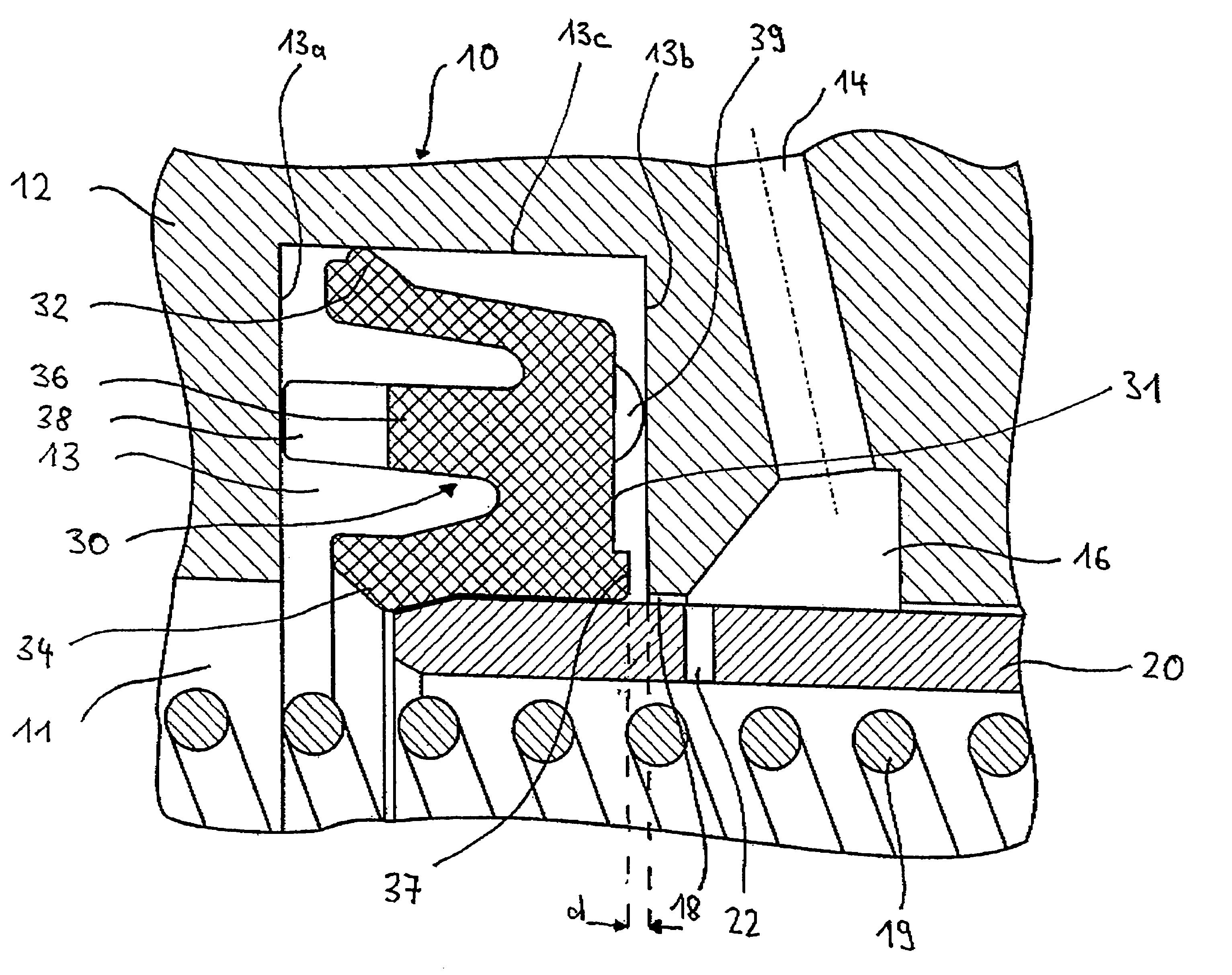
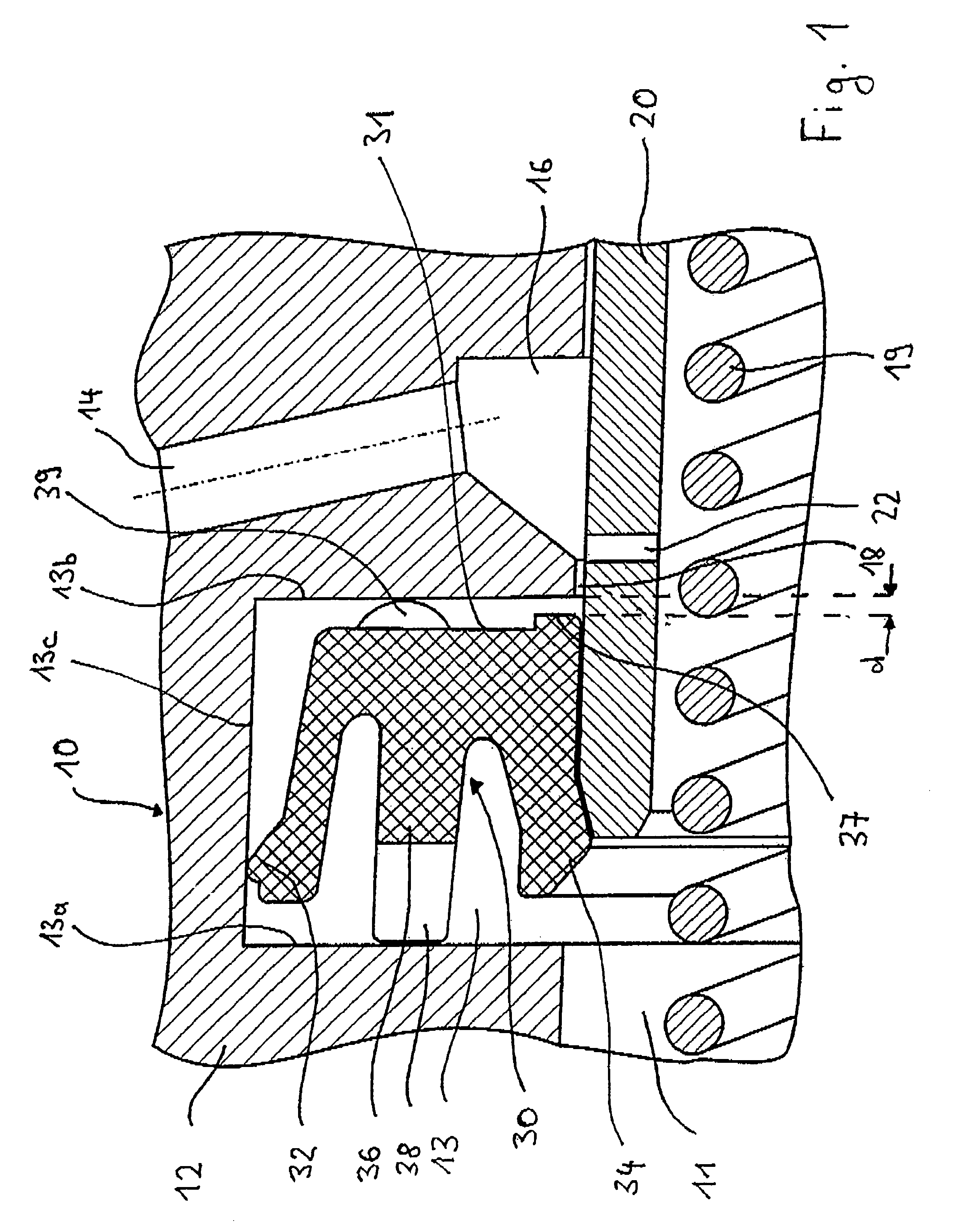
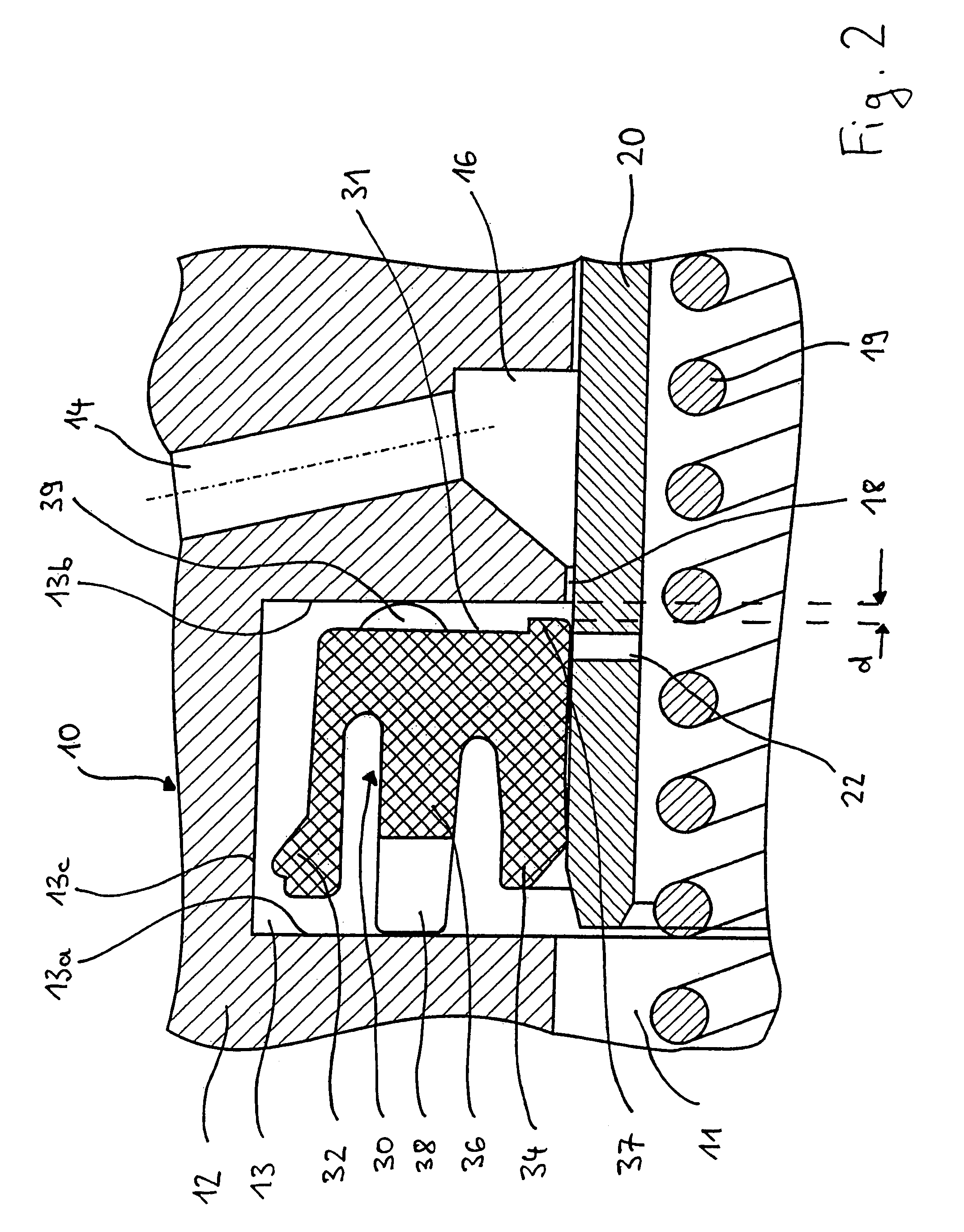
[0026]FIG. 1 shows, in axial section, a brake cylinder, which for instance can be in plunger or tandem form as a main brake cylinder 10 for hydraulic motor vehicle braking systems. In the case of a tandem main brake cylinder, the two pressure circuits, which are arranged one behind the other, are almost identical regarding their construction and functioning. The following description is therefore restricted to only one pressure circuit. Below, only those features of the main brake cylinder 10 which are relevant with respect to the invention are described, since the functioning of such main brake cylinders is known to the person skilled in the art.

[0027]FIG. 1 shows, in axial section, a main brake cylinder 10, which has a housing 12 in cylindrical form, in which a pressure piston 20 is arranged so that it can move. A force is applied to the pressure piston 20 by a brake pedal, with a brake booster (not shown) connected between them. If the main brake cylinder 10 is in tandem construc...


PUM


Abstract

A sealing element seals a pressure piston which is movably arranged in a housing of a brake cylinder. The sealing element may be inserted into a ring-shaped groove which is provided in the housing. The sealing element includes an outer sealing lip for contact with a floor of the ring-shaped groove, an inner sealing lip for contact with the pressure piston, and a sealing element back. At least one non-sealing spacer element is provided on the sealing element back.

Description

CROSS-REFERENCE TO RELATED APPLICATIONS[0001]This application claims priority to German Patent Application No. 10 2006 040 487.4 filed Aug. 30, 2006, the disclosures of which are incorporated herein by reference.BACKGROUND OF THE INVENTION[0002]This invention concerns a sealing element for sealing a pressure piston which is movably arranged in a housing of a brake cylinder, it being possible to insert said sealing element into a ring-shaped groove which is provided in the housing. The sealing element includes an outer sealing lip for contact with a floor of the ring-shaped groove, an inner sealing lip for contact with the pressure piston, and a sealing element back. The invention also concerns a brake cylinder, in particular for hydraulic motor vehicle braking systems, into which such a sealing element for sealing a movably arranged pressure piston is inserted.[0003]A sealing element and a brake cylinder of the above-mentioned type are described in, for instance, WO 2005 / 019007, and...

Claims


Application Information

Patent Timeline
Patent Type & Authority Patents(United States)
IPC IPC(8): B60T11/236
CPCB60T11/228B60T11/236F16J15/56F16J15/3236F16J15/164
Inventor STRUSCHKA, MARTIN
Owner LUCAS AUTOMOTIVE GMBH
Why Eureka
Try Eureka