
Micromachined electron or ion-beam source and secondary pickup for scanning probe microscopy or object modification

a micro-machined electron or ion beam technology, applied in the direction of instruments, mechanical measurement arrangements, mechanical roughness/irregularity measurements, etc., can solve the problems of insufficient speed, sample preparation, cost and destructive nature of electron beams, ion beams, and dual ion and electron beam systems. , the high beam energy required for classical e-beam or ion beam systems is injurious or deadly to the subject, and the effect of fast optical ga

Inactive Publication Date: 2011-06-14
KLEY VICTOR B
View PDF27 Cites 9 Cited by
  • Summary
  • Abstract
  • Description
  • Claims
  • Application Information

AI Technical Summary

Benefits of technology

"The present invention provides a system for low energy high resolution electron beam or ion beam devices that operate outside a vacuum. The system can be incorporated into a scanning probe microscope while retaining its functionality. The beam technology can be manufactured at a low cost and can operate in a fluid such as water. The system can also support extremely fast pulse operation and can provide simultaneous inspection, analysis, probing, manipulating, modifying, inducing chemical or biological or catalytic change using various SPM techniques. The system includes a sealed system for electron beams in which there is a vacuum or chosen gas. The invention also provides a point beam emitter that is extremely small using a carbon nanotube grown or attached to the emitter structure. The device can be used for imaging and exposing samples at ambient pressures, humidity, and temperatures. The system can be quickly and easily setup and sample exchange is simple. The invention also provides a thin window or a long high-Z path to shield the sample area from penetrating radiation."

Problems solved by technology

Manufacturing and other processes pertaining to scanning probe microscopy, nanomachining, micromachining, machining, optics, biotechnology, and biomedicine benefit from electron and / or ion beam imaging and modification but are not well served by speed, sample preparation, cost and destructive nature of present day electron beam, ion beam, and dual ion and electron beam systems.
Especially in the biological world and increasingly in the semiconductor world high beam energies required for classical e-beam or ion beam systems are injurious or deadly to the subject, inspection requirements or production material under there influence.

Method used


Image

  • Micromachined electron or ion-beam source and secondary pickup for scanning probe microscopy or object modification
  • Micromachined electron or ion-beam source and secondary pickup for scanning probe microscopy or object modification
  • Micromachined electron or ion-beam source and secondary pickup for scanning probe microscopy or object modification

Examples


Embodiment Construction

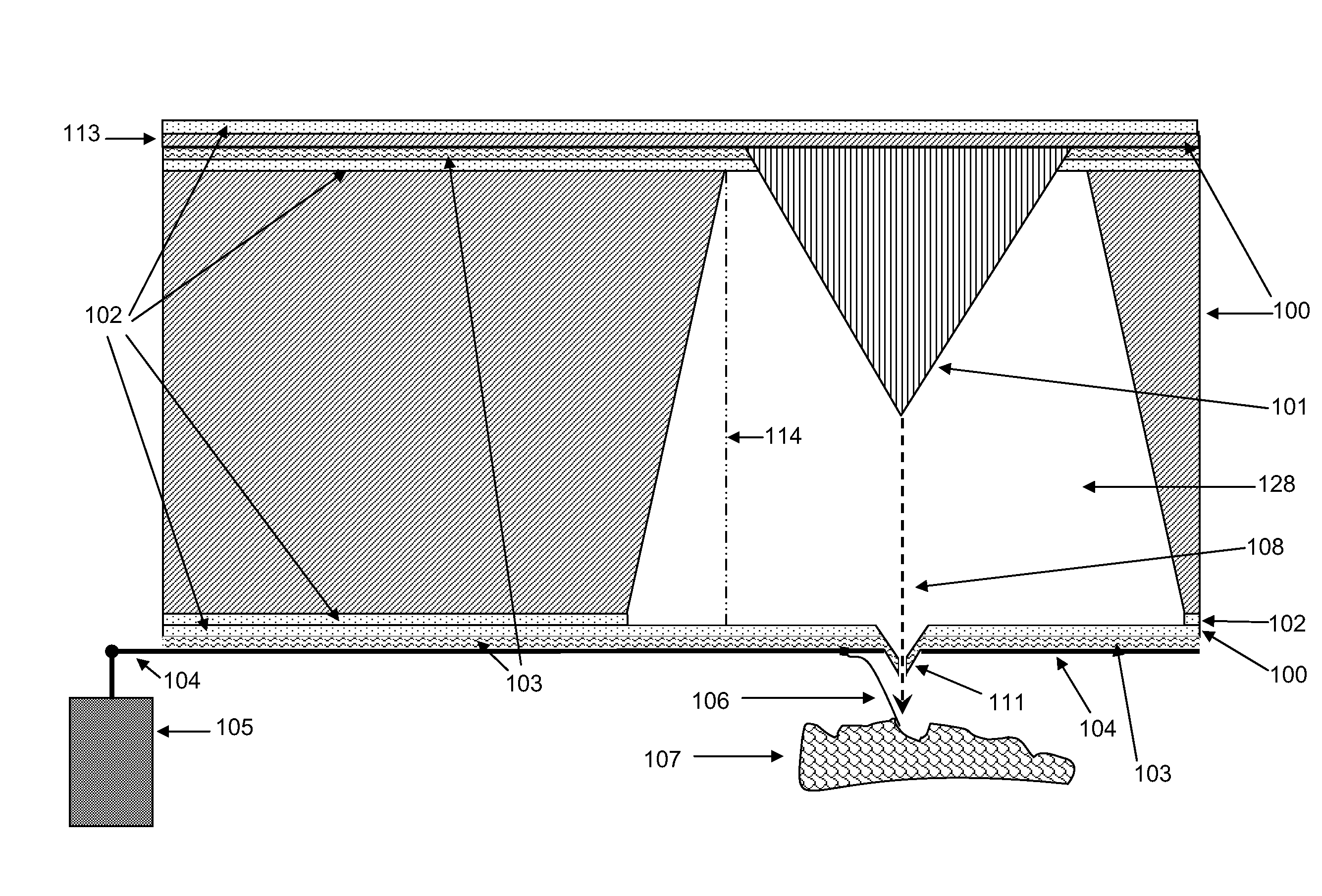
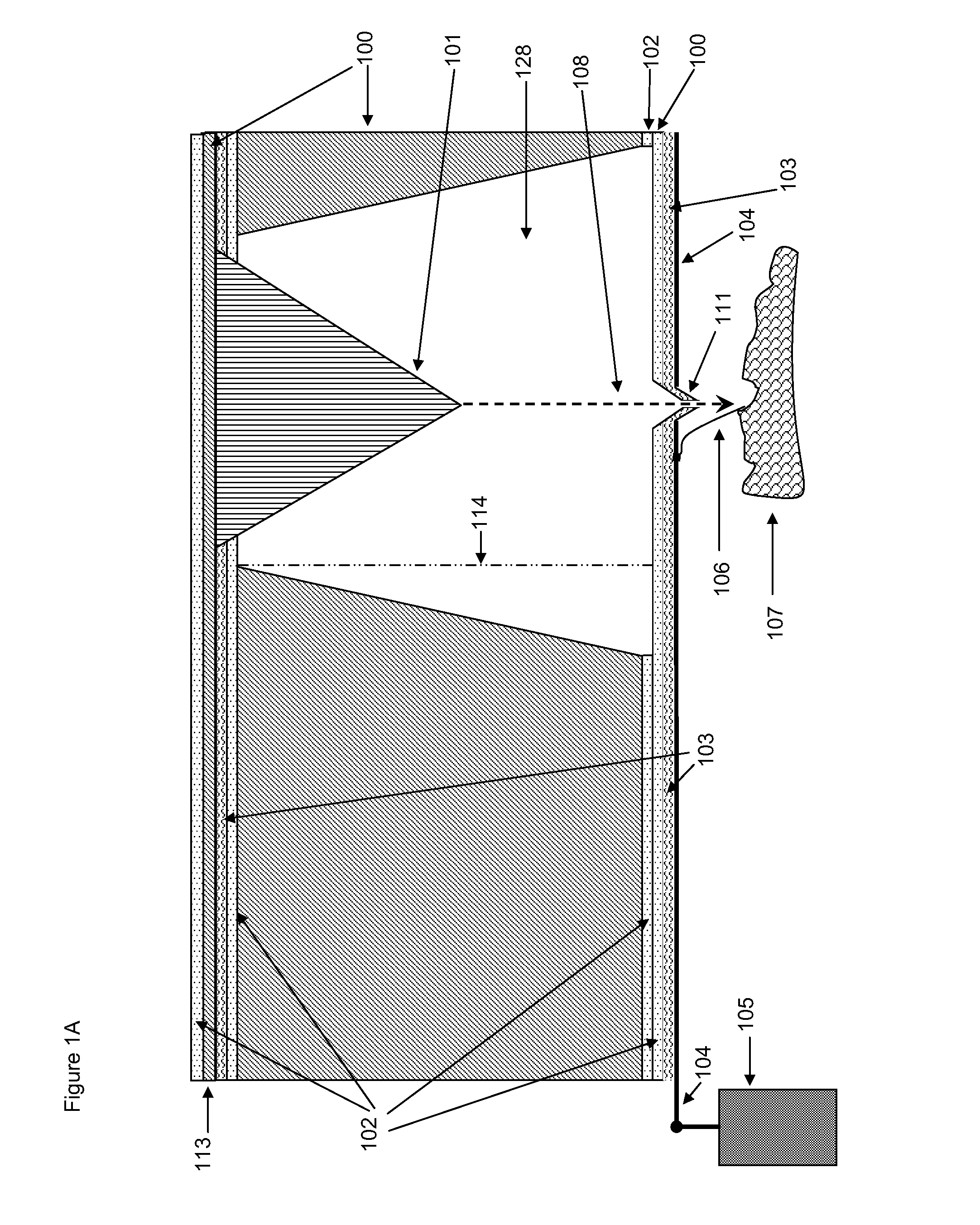
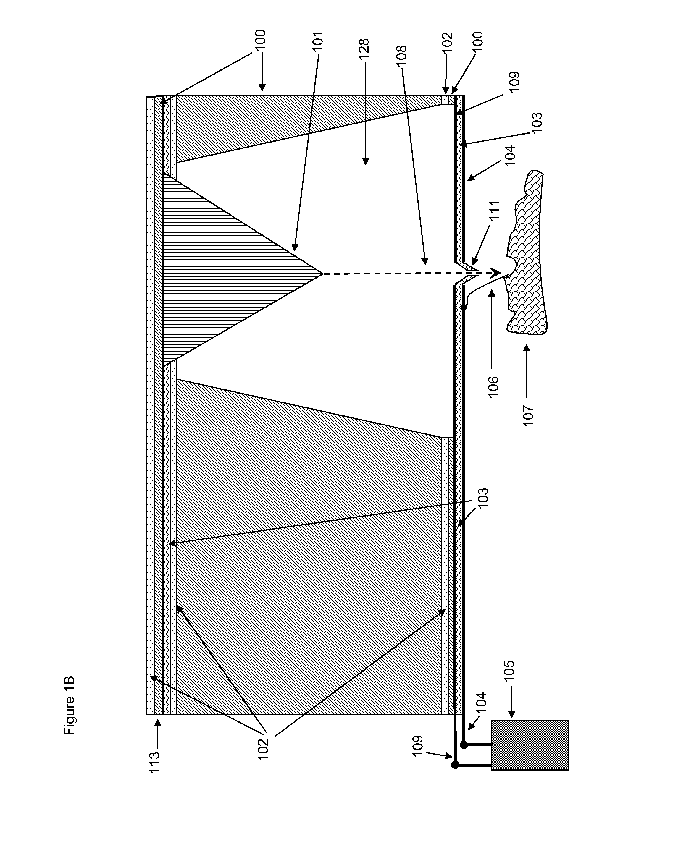
[0047]FIG. 1A shows an alternative form for an electron and / or ion beam (108) device with integrated scanning tip (111). In operation this collection of elements is part of a complete SPM tip assembly (200, shown in FIGS. 2L and 2M) and the electrical connections (113, 104) and with fluid channel 114 (also shown in FIG. 1G) feeding cavity (128) with He, Ar, N2, kerosene, megaohm resistivity water, oil, silicone oil, or CO2 or any other gas or liquid at positive pressures in air and negative pressures in a suitable fluid (example as above). In one mode of operation a gas Ar at 1.1 atmospheres flows from some feed source through the tip assembly and out through micromachined passage 114 into the cavity 128 and out through the hole in tip 111. After scavenging all or most O2 from the cathode 101 which may be intrinsic diamond, boron doped diamond, nitrogen doped diamond, phosphorous doped diamond, any metal, silicon carbide, silicon nitride, carbon or boron nanotubes, or any material s...


PUM

PropertyMeasurementUnit
Pierce angleaaaaaaaaaa
lengthsaaaaaaaaaa
lengthaaaaaaaaaa

Abstract

An e-beam or ion beam imaging and exposure system is built into the end of an AFM cantilever which images using the scanning capabilities built into the AFM. In one embodiment, a boron doped diamond cold cathode is formed into the cantilever with an associated accelerating electrode and secondary electron collection electrode. The assembly is brought within a few nanometers of the object to be imaged or exposed using the AFM. One or more gas channels built into the cantilever assembly provide a positive pressure of inert gas to prevent oxidative erosion of the cold cathode and can bleed any surface charge build up on the sample surface. After secondaries are collected the cantilever is moved to the next area to be exposed.

Description

CROSS-REFERENCES TO RELATED APPLICATIONS[0001]This application claims the benefit of the following five U.S. Provisional Patent Applications:[0002]Application No. 60 / 680,687, filed May 13, 2005, entitled “Micromachined Electron or Ion Beam Source and Secondary Pickup for Scanning Probe Microscopy or Object Modification”;[0003]Application No. 60 / 681,720, filed May 16, 2005, entitled “Micromachined Electron or Ion Beam Source and Secondary Pickup for Scanning Probe Microscopy or Object Modification”;[0004]Application No. 60 / 687,269, filed Jun. 3, 2005, entitled “Micromachined Electron or Ion Beam Source and Secondary Pickup for Scanning Probe Microscopy or Object Modification”;[0005]Application No. 60 / 711,899, filed Aug. 25, 2005, entitled “Manufacturing of Micro-Objects Such As Miniature Diamond Tool Tips”; and[0006]Application No. 60 / 723,643, filed Oct. 4, 2005, entitled “Micromachined Electron or Ion Beam Source and Secondary Pickup for Scanning Probe Microscopy or Object Modificat...

Claims


Application Information

Patent Timeline
Patent Type & Authority Patents(United States)
IPC IPC(8): G01N23/00
CPCB82Y35/00G01Q30/02G01Q60/38H01J37/261H01J37/28H01J2237/2583H01J2237/1503H01J2237/2803H01J2237/1205
Inventor KLEY, VICTOR B.
Owner KLEY VICTOR B
Learn More