Shaft seal device
a seal device and shaft technology, applied in the direction of liquid fuel engines, machines/engines, rotary piston liquid engines, etc., can solve the problems of accelerating abrasion of sliding seal faces, unable to prevent some impurities, and impurities, in particular, easily get caught on seal faces, etc., to prevent heat-induced heat-induced heat-induced heat-induced heat-induced heat-induced heat-induced heat-induced heat-induced heat-induced heat-induced heat-induced hea
- Summary
- Abstract
- Description
- Claims
- Application Information
AI Technical Summary
Benefits of technology
Problems solved by technology
Method used
Image
Examples
embodiment 1
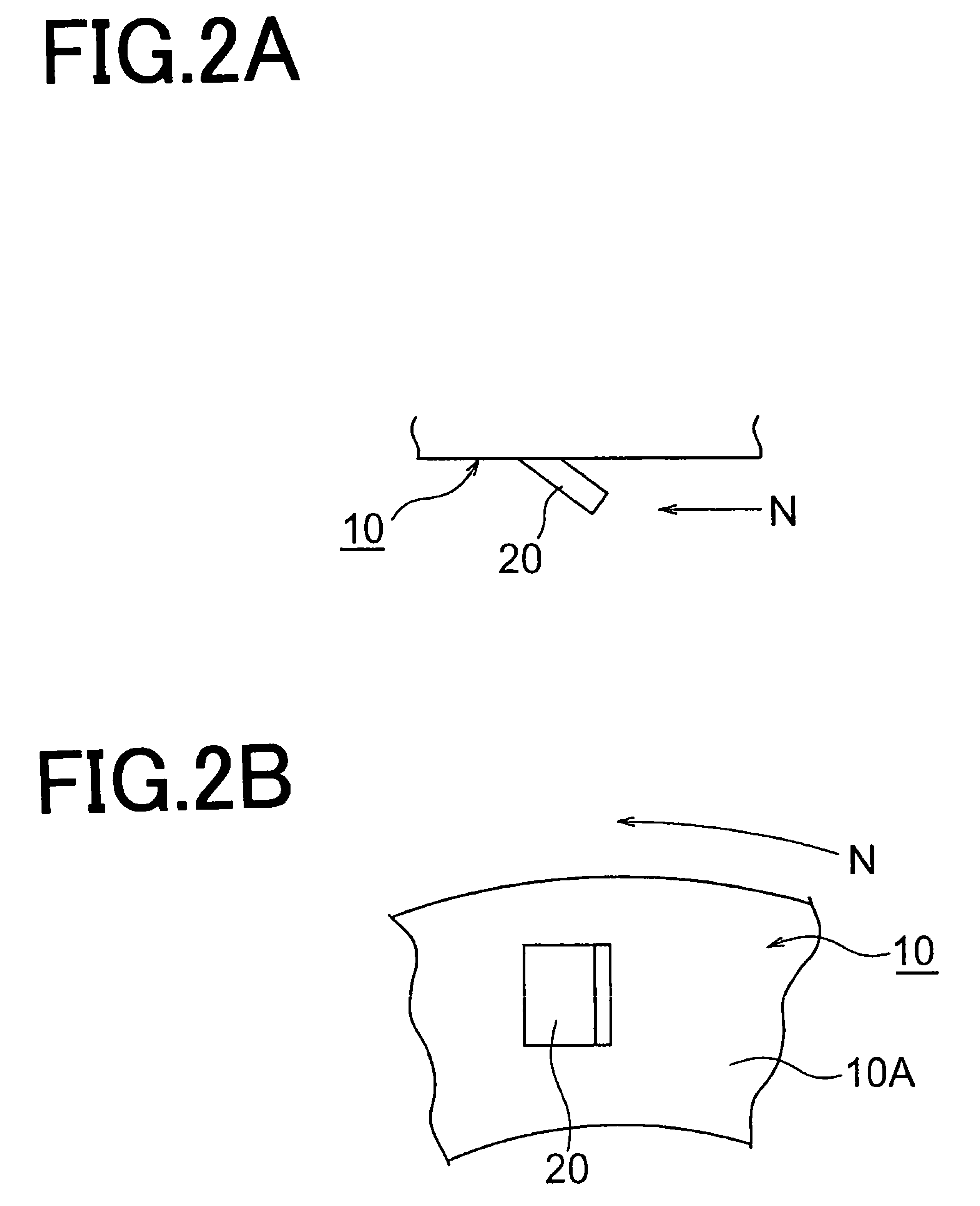
[0018]First, a shaft seal device of the embodiment 1 related to the present invention will be described. FIG. 1 shows a cross sectional view of a half portion of a shaft seal device 1. In FIG. 1, a rotary shaft 50 is mounted in a bearing bore 61 in a housing 60. A seal sleeve 10 fitted to the rotary shaft 50 is fabricated in a cylindrical form out of a stainless steel sheet. Both ends of a cylindrical portion 10E of the seal sleeve 10 are bent radially outward. A rotary wing 10A which is inflected at one end of the cylindrical portion 10E is structured so as to form an L-shape cross section from the end and to have a U-shape cross section in its entirety including the end portion so that a seal face 3A1 of an annular lip member 3A can be inserted thereinto. A region defined within the rotary wing 10A of U-shape design is referred to as a seal face region L2. As shown in FIG. 2A and FIG. 2B, there is disposed a discharge means 20 on the radially extending side wall of the rotary wing...
embodiment 2
[0026]Next, a shaft seal device 1 of the embodiment 2 related to the present invention will be described. FIG. 3 is a cross sectional view of a half portion of the shaft seal device 1 related to the embodiment 2. What makes FIG. 3 different from FIG. 1 is that there is disposed a discharge means 20 on the diameter surface of the partitioning portion 10A1 of the rotary wing 10A. The discharge means 20, as shown in FIG. 4, is fabricated by inflecting a portion of the partitioning portion 10A1 along the circumferential surface of the partitioning portion 10A1 to give a fin-like shape. A plurality of fins are provided along the circumferential surface of the partitioning portion 10A1. The discharge means 20 can alternatively be fabricated by means of deep drawing applied to a portion of the partitioning portion 10A1 in order to form fin-shaped projections. Multiple rows of discharge means 20, 2 to 3 rows aligned in the axial direction, can be constructed on the periphery surface of the ...
PUM
 Abstract
Description
Claims
Application Information
 - R&D
- Intellectual Property
- Life Sciences
- Materials
- Tech Scout
- Unparalleled Data Quality
- Higher Quality Content
- 60% Fewer Hallucinations
Browse by: Latest US Patents, China's latest patents, Technical Efficacy Thesaurus, Application Domain, Technology Topic, Popular Technical Reports.
© 2025 PatSnap. All rights reserved.Legal|Privacy policy|Modern Slavery Act Transparency Statement|Sitemap|About US| Contact US: help@patsnap.com


