
Coated electrode array having uncoated electrode contacts

a technology of uncoated electrodes and electrode contacts, which is applied in the direction of head electrodes, internal electrodes, therapy, etc., can solve the problems of conductive hearing loss, impeded normal mechanical pathways for sound to reach the hair cells in the cochlea, and deafness sensorineural hearing loss, so as to improve the performance of the electrode array, prevent neural degeneration, and promote neural regeneration

Active Publication Date: 2011-05-24
ADVANCED BIONICS AG
View PDF94 Cites 47 Cited by
  • Summary
  • Abstract
  • Description
  • Claims
  • Application Information

AI Technical Summary

Benefits of technology

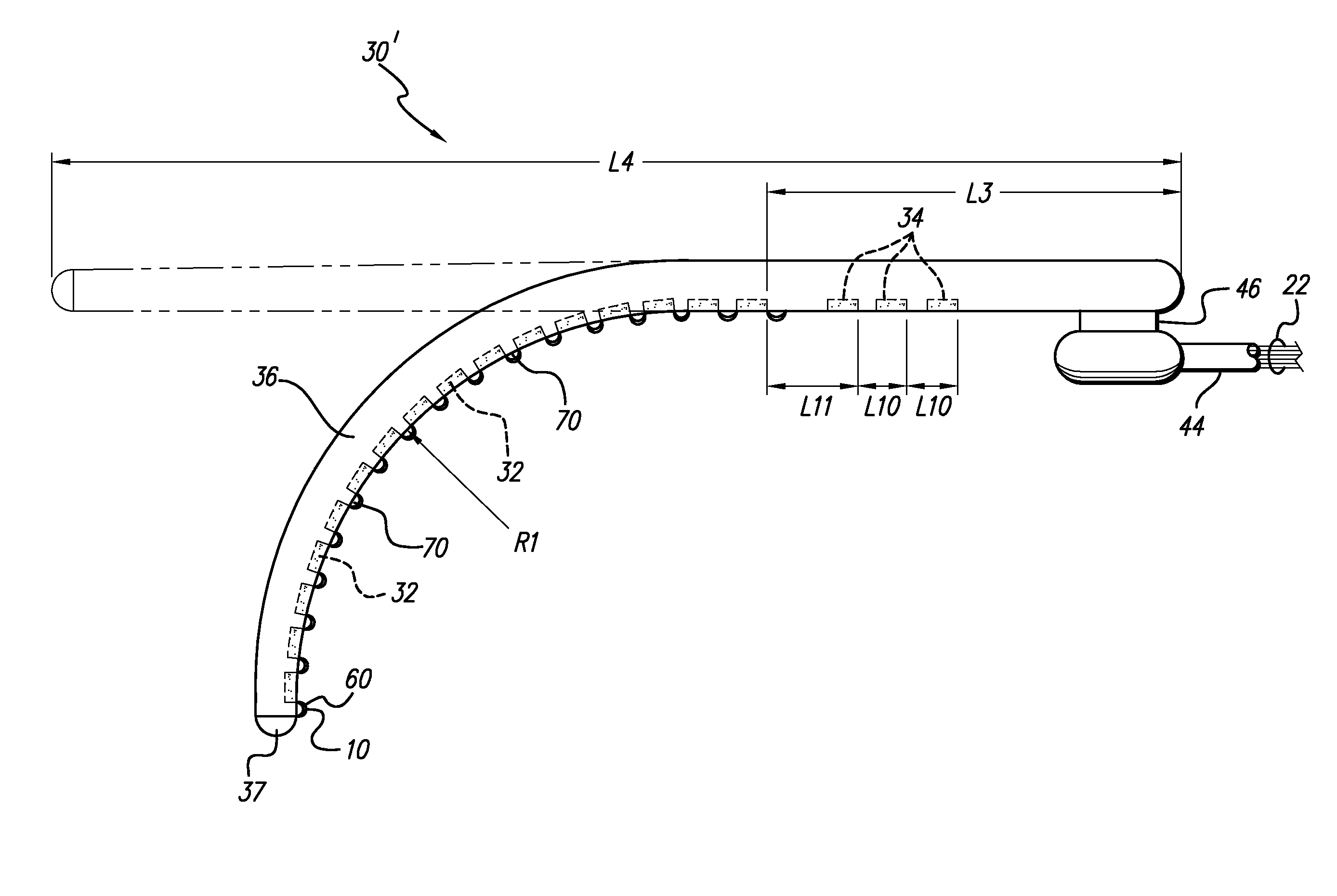
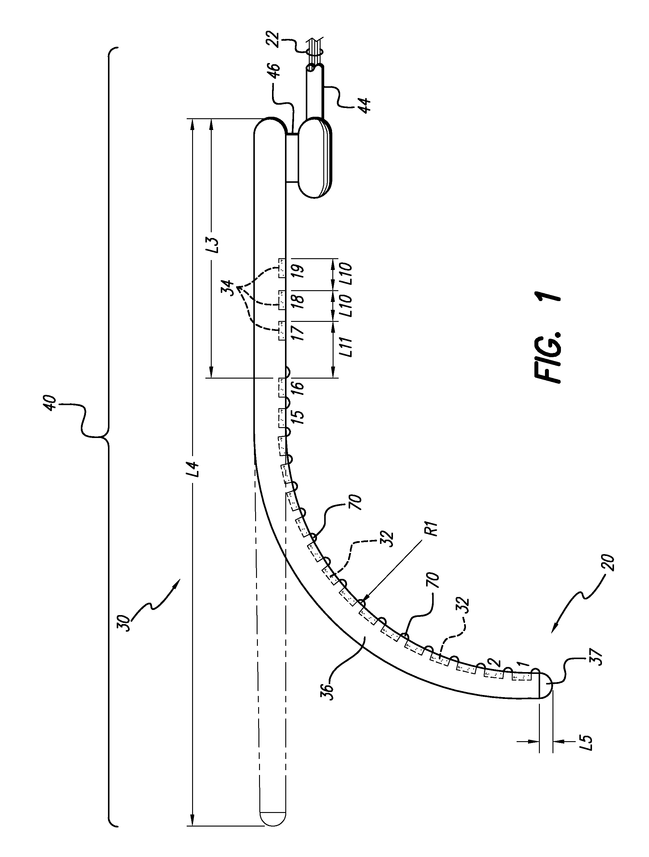
The teachings of the present disclosure addresses the above and other needs by providing a universal electrode array, adapted for insertion into either a left or right cochlea, which provides improved stability of electrode contact direction. All of the electrode contacts are spaced apart along one edge or side of the array, termed the “medial side”. The structure of the electrode array facilitates bending of the array with the electrode contacts on the inside of the bend, yet deters flexing or twisting of the array that would tend to position or point the electrode contacts away from the inside of the bend. Hence, when inserted into the scala tympani duct of a cochlea, all of the electrode contacts on the medial side of the array generally face the modiolus wall of the cochlea. Furthermore the electrode side includes a bioresorbable coated material which, over time, is absorbed and thereby reduces pressure buildup within the cochlea.
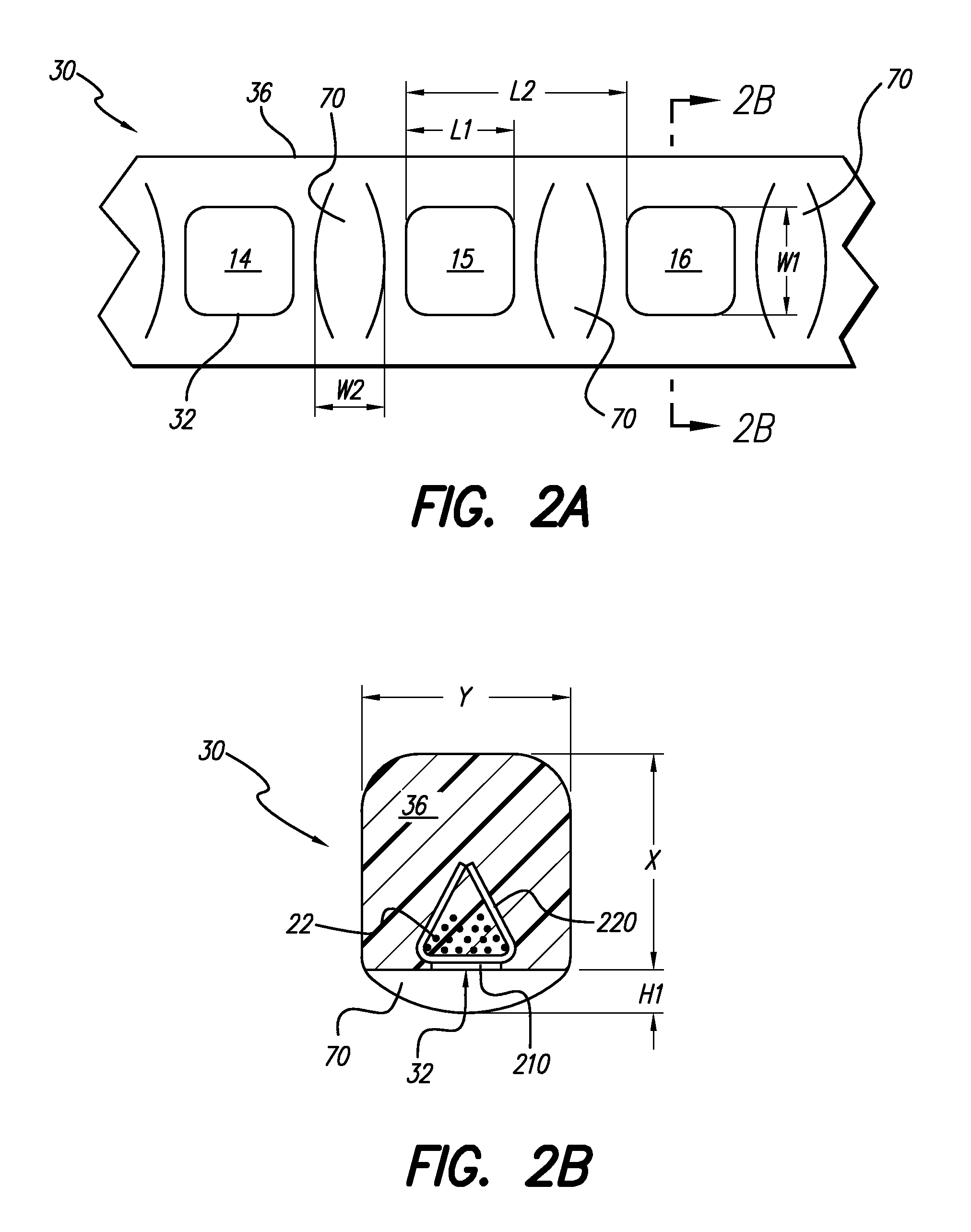
In one embodiment, small non-conductive bumps or humps are formed in the carrier between the electrode contact areas on the medial side of the array. These small bumps are made, e.g., from a soft silicone rubber, or equivalent substance. When inserted into the cochlea, the small bumps serve as non-irritating stand-offs, or spacers, that keep the electrode contacts near the modiolus wall, but prevent the electrode contacts from actually touching the modiolus wall. The bumps may also serve as dielectric insulators that help steer the stimulating electrical current in the desired direction, towards the modiolus wall, as taught, e.g., in U.S. Pat. No. 6,112,124, incorporated herein by reference. Furthermore the non-conductive bumps are coated with a bioresorbable material with a defined thickness which, over time, is absorbed to thereby reduce chronic placement pressure which may have been induced during the insertion of the electrode array into the cochlea. The bioresorbable material may also serve as a carrier for drugs and other materials that would improve performance of the electrode array. Such drugs are used to elicit a desired therapeutic or other result, e.g., to inhibit fibrous tissue or bone growth in the vicinity of the electrode contacts; or to promote healing of damaged tissue in the region of the electrode contacts, or to prevent infection and discomfort to the patient.
It is an additional feature of the teachings of the present disclosure to provide a bioresorbable material coated on the surface of the non-conductive bumps which may serve as carriers for drugs or other materials that can improve the performance of the electrode array. Representative drugs that may be used to coat the electrode array and / or the individual non-conductive bumps in accordance with this aspect of the teachings of the present disclosure include selected steroids, either naturally occurring or synthetic, or a Neuro-trophin selected to prevent neural degeneration and / or to promote neural regeneration.
It is a further feature of the teachings of the present disclosure to provide an electrode array used in SCS applications which includes a bioresorbable material on the electrode contact side of the electrode array to further enhance the performance of the SCS stimulation therapy.

Problems solved by technology

Of these, conductive hearing loss occurs where the normal mechanical pathways for sound to reach the hair cells in the cochlea are impeded, for example, by damage to the ossicles.
In many people who are profoundly deaf, however, the reason for their deafness is sensorineural hearing loss.
These people are unable to derive any benefit from conventional hearing aid systems, no matter how loud the acoustic stimulus is made, because their mechanisms for transducing sound energy into auditory nerve impulses have been damaged.
Thus, in the absence of properly functioning hair cells, there is no way auditory nerve impulses can be generated directly from sounds.
In practice, this goal tends to be difficult to realize because of the anatomy of the cochlea.
Unfortunately, while the electrode array with spiral-shaped carrier shown in the '647 patent represents a significant advance in the art, there exists lack of sufficient shape memory associated with the carrier to allow it to return to its original curvature (once having been straightened for initial insertion) with sufficient hugging force to allow it to wrap snugly against the modiolus of the cochlea.
Thus, while it has long been known that an enhanced performance of a cochlear implant can be achieved by proper placement of the electrode contacts close to the modiolar wall of the cochlea, two main problems have faced designers in attempting to achieve this goal.
First, it is extremely difficult to assemble electrode contacts on the medial side of the an electrode array, facing the modiolus of the cochlea.
Second, heretofore there has either been the need for application of an external (and perhaps unsafe) force, or a lack of sufficient shape memory, to allow the electrode (after initial straightening to facilitate insertion) to assume or return to the desired curvature needed to place the electrodes against the modiolar wall so that the curvature wraps snugly around the modiolus of the cochlea.
As a result, the electrode contacts of the prior art electrodes are generally positioned too far way from the modiolar wall.
During the insertion procedure of the modular hugging electrode, a pressure build-up occurs which may potentially damage the modiolar wall structure of the cochlea.
The pressure may become chronic causing discomfort and infection to the patient.

Method used


Image

  • Coated electrode array having uncoated electrode contacts
  • Coated electrode array having uncoated electrode contacts
  • Coated electrode array having uncoated electrode contacts

Examples


Embodiment Construction

The following description is of the best mode presently contemplated for carrying out the invention. This description is not to be taken in a limiting sense, but is made merely for the purpose of describing the general principles of the invention. The scope of the invention should be determined with reference to the claims.

For illustration purposes, the following description is provided in conjunction with a Cochlear Stimulation (CS) system. Other types of stimulation systems may also be used such as, but not limited to, spinal cord stimulation systems, cardiac stimulation systems, peripheral nerve stimulation systems, brain stimulation systems and microstimulators. The disclosure presented herein, is further directed to implantable leads for use with implantable or external stimulators. The leads include all neurostimulation leads, e.g., cochlear leads, spinal cord stimulation leads, or leads used in the body to stimulate muscle or nerve tissue. One type of lead, used as an exempla...


PUM


Abstract

Implantable electrode leads, e.g. cochlear, spinal cord stimulation, or any type of neurostimulation leads, used in a patient's body to stimulate muscle or nerve tissue, provide enhanced stimulation for treating, e.g., hearing loss or chronic pain. One such lead includes, an implantable electrode array, adapted for insertion into a cochlea, which lead provides improved stability of electrode contact direction. In-line electrodes are spaced-apart along one side of a flexible carrier having non-conductive bumps coated with a bioresorbable material spaced apart between each electrode contact. Over time the bioresorbable material is absorbed thereby reducing chronic placement pressure caused during the insertion of the electrode array into the cochlea. The bioresorbable material may also serve as a carrier for drugs or other materials that would improve performance of the electrode for any type of lead.

Description

BACKGROUND OF THE INVENTIONThe teachings of the present disclosure relate to external or implantable stimulation devices, e.g., cochlear prosthesis used to electrically stimulate the auditory nerve, spinal cord stimulation (SCS) devices used to provide therapy along the dura of the spinal cord, or other types of neurostimulation devices used to provide therapy to muscles or nerve tissue. More particularly, the teachings of the present disclosure relate to an implantable electrode array for use with, e.g., a cochlear stimulator, an SCS stimulator, or any type of neurostimulation device used in the body to stimulate muscle or nerve tissue. Such stimulation devices, e.g., cochlear stimulator, are designed to place the electrode contacts of the electrode array generally along one side of the array so that when the array is implanted, e.g., in the cochlea, or other body cavity, the side of the array whereon the electrode contacts are located can be positioned in close proximity to the ce...

Claims


Application Information

Patent Timeline
IPC IPC(8): A61N1/372
CPCA61N1/0558A61N1/0541A61N1/0551
Inventor HARRISON, WILLIAM VANBROOKSCOLVIN, MICHAEL SKUZMA, JANUSZ ABALKANY, THOMAS J
Owner ADVANCED BIONICS AG
Learn More