
Wireless illuminated indicators for motorcycle helmets

Active Publication Date: 2011-05-24
GARVEY BRIAN J
View PDF9 Cites 28 Cited by
  • Summary
  • Abstract
  • Description
  • Claims
  • Application Information

AI Technical Summary

Benefits of technology

[0013]A further aspect of the wireless retrofitted brake light for motorcycle helmet is to elevate location of the light display unit indicators to provide increased visibility thereto following traffic.
[0014]A further aspect of the wireless retrofitted brake light for motorcycle helmet is to reduce motorcycle user death and injury by providing a more visible brake and turn signal indicator to following traffic. This increased visibility will lead to faster reaction time and increased braking time for following motorists. The additional split seconds of reaction time afforded by the current invention to following motorists may be all that is needed to help save lives.
[0022]Still a further aspect of the wireless retrofitted brake light for motorcycle helmet is that connection from the connection wiring harness to the associated corresponding wire or electrical connection on the motorcycle would be made in such a manner so that the integrity of the original motorcycle wiring is not negatively impacted.
[0028]Yet a further object of the wireless retrofitted brake light for motorcycle helmet comprises an illumination means array as an output of the receiver module. The illumination means array comprises high-intensity light emitting diodes (LED's) as shown due to their low power consumption, long life and good visibility. Other illumination means can also used.
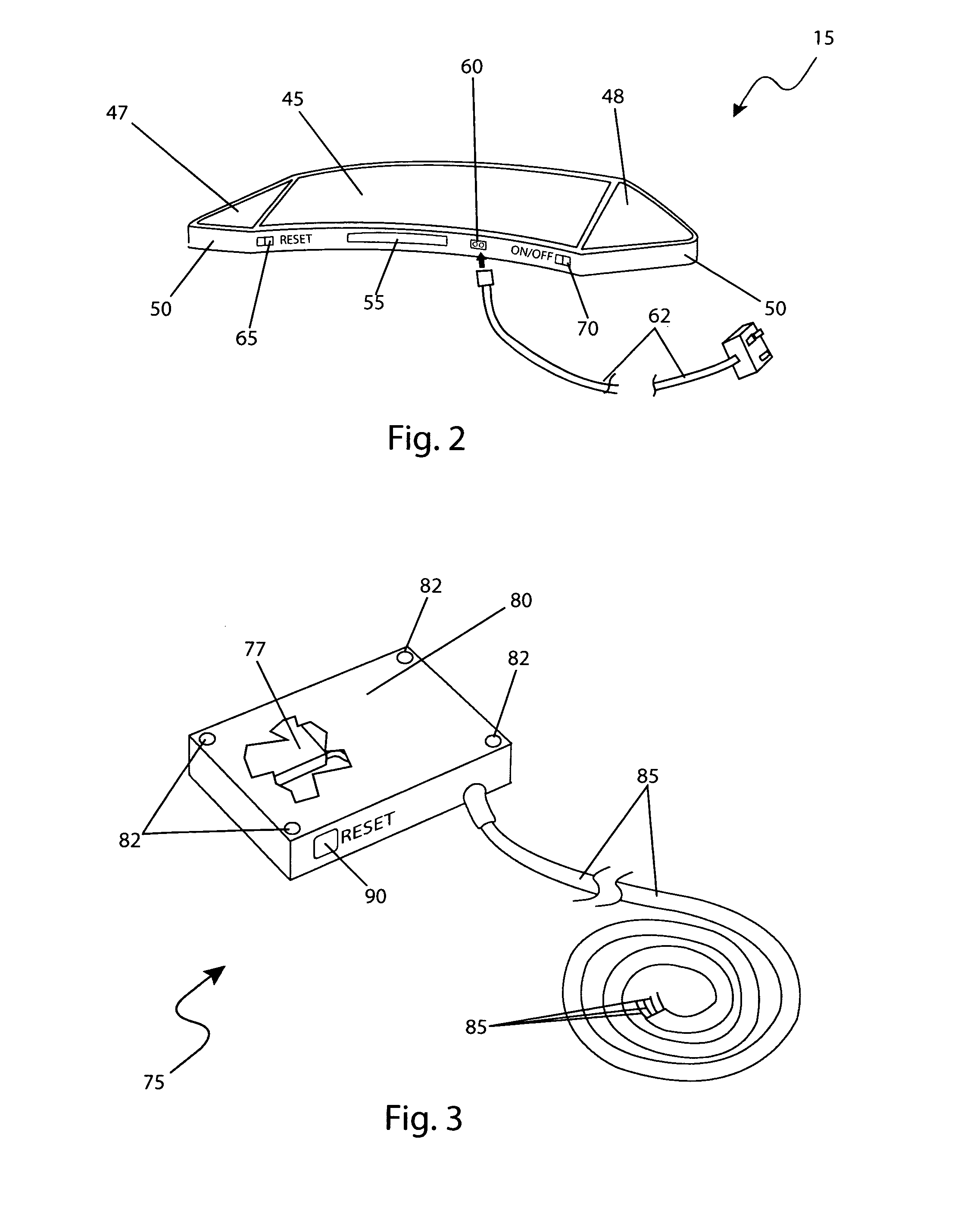
[0029]A method for installing and utilizing a wireless retrofitted brake light for motorcycle helmet that may be used by performing the following steps: procuring a particular model of the wireless retrofitted brake light for motorcycle helmet; fastening the light display unit to the motorcycle helmet using the adhesive element; charging the rechargeable battery pack by connecting the recharge unit thereto the recharging port on the flexible backplane enclosure and plugging said recharge unit into a common household 120 V outlet; installing the transmitter assembly by positioning in a secure, but accessible location, on the motorcycle; routing the connection wiring harness to a suitable location where electrical connections can be made to the motorcycle wiring system comprising the following four signals; (1) ground connection, (2) brake signal connection, (3) right turn signal connection, and (4) left turn signal connection; performing the pairing process to enable the association of one (1) transmitter unit thereto one receiver module; and, benefiting from improved motorcycle riding safety due to increased visibility of braking and turning indicators afforded a user of the present invention.
[0031]A further object of the wireless retrofitted brake light for motorcycle helmet is to comprise a pairing process to align the transmitter unit and receiver in combination to each other to prevent interference therefrom additional users of the apparatus being in close proximity. In this manner, two motorcycles, both equipped with the apparatus can ride near one another without causing cross-activation. Such a process is necessary when buying a new helmet or motorcycle which may have the features of the apparatus already installed. The pairing feature also allows the light display unit to be used with multiple or different transmitters assemblies provided on different motorcycles.

Problems solved by technology

In view of the foregoing disadvantages inherent in the prior art, it has been observed that there is need for wireless retrofitted brake light that attaches to a motorcycle helmet.

Method used


Image

  • Wireless illuminated indicators for motorcycle helmets
  • Wireless illuminated indicators for motorcycle helmets
  • Wireless illuminated indicators for motorcycle helmets

Examples


Embodiment Construction

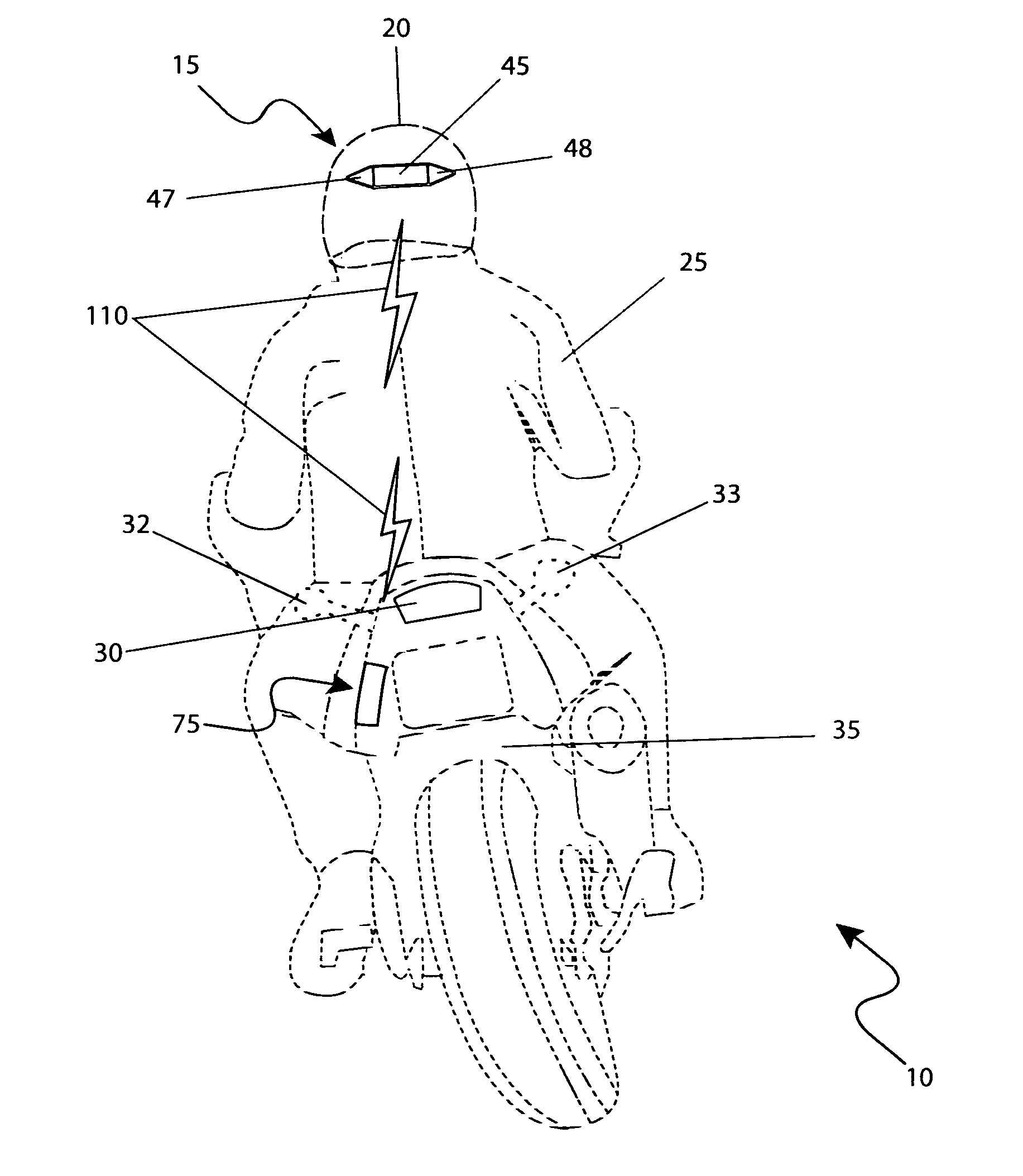
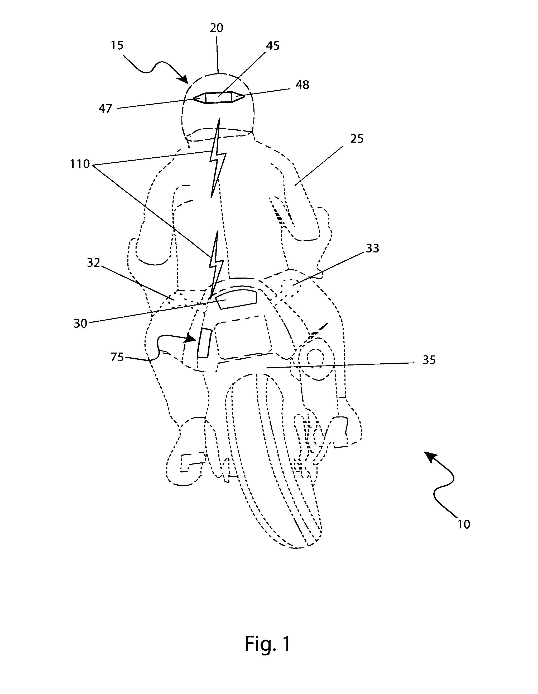
[0041]The best mode for carrying out the invention is presented in terms of its preferred embodiment, herein depicted within FIGS. 1 through 4 and FIG. 6 as well as in terms of its alternate attachment method, herein depicted within FIG. 5. However, the invention is not limited to the described embodiment and a person skilled in the art will appreciate that many other embodiments of the invention are possible without deviating from the basic concept of the invention, and that any such work around will also fall under scope of this invention. It is envisioned that other styles and configurations of the present invention can be easily incorporated into the teachings of the present invention, and only one particular configuration shall be shown and described for purposes of clarity and disclosure and not by way of limitation of scope.

[0042]The terms “a” and “an” herein do not denote a limitation of quantity, but rather denote the presence of at least one of the referenced items.

[0043]T...


PUM


Abstract

A wireless braking and turning indicator attached to a motorcycle helmet and a motorcycle mounted transmitter is herein disclosed. An illumination assembly is attached on the rear surface of the helmet by means of either double-sided adhesive or an elastic band. An integral wireless receiver powered by a rechargeable battery receives a signal from a transmitter mounted on the motorcycle and electrically connected to the brake and turn signal indication circuits. In such a manner, the helmet-mounted light assembly will illuminate whenever the motorcycle brakes are applied in much the same manner as a center-mounted high brake light on motor vehicles. Turning direction is also indicated in like manner. When used, the rider's head is at a sufficient elevation to be easily seen by following traffic.

Description

RELATED APPLICATIONS[0001]The present invention was first described in and claims the benefit of U.S. Provisional Application No. 60 / 923,528 filed on Apr. 16, 2007, the entire disclosures of which are incorporated herein by reference.FIELD OF THE INVENTION[0002]The present invention relates generally to a wireless illumination display system detachably mounted thereto a motorcycle helmet comprising a motorcycle mounted transmitter assembly, an electrical connection means thereto existing motorcycle brake and turn signal indicators, a receiver assembly integral therein an illuminating display unit powered by rechargeable power source.BACKGROUND OF THE INVENTION[0003]Automobile accidents are among the leading causes of injury and death in the United States today. According to the United States Department of Transportation, Motorcycle fatalities and the related fatality rate have been significantly increasing over the last ten (10) years. Between 1996 and 2005, motorcyclist fatalities ...

Claims


Application Information

Patent Timeline
IPC IPC(8): B60Q1/34
CPCA42B3/0453B60Q1/2676B62J2006/008B60Q2900/30B62J6/165
Inventor ARAUZA, ALEXANDER M.
Owner GARVEY BRIAN J
Learn More