
System and method for camera calibration and images stitching

a camera and image technology, applied in the field of color calibration technique and stitching technique for use with omnidirectional cameras, can solve the problems of inadvertent change of settings between pictures, significant discontinuities between images, and still sometimes differences in color between images, so as to reduce the cost of computer processing units, reduce the effect of vignetting effect, and reduce the cost of processing units

Inactive Publication Date: 2011-05-03
MICROSOFT TECH LICENSING LLC
View PDF113 Cites 22 Cited by
  • Summary
  • Abstract
  • Description
  • Claims
  • Application Information

AI Technical Summary

Benefits of technology

[0018]The color calibration technique discussed above is advantageous in that it corrects the color in images before they are digitized, in real time. That is, the analog images are color corrected by the analog front end of the camera before being digitized. Additionally, since the technique requires very little processing it calibrates image color at very little Computer Processing Unit (CPU) cost. Besides saving CPU processing, superior image quality can be achieved because the color of the images are corrected before the signal is quantized (i.e., errors are corrected early in the process before they become compounded and exaggerated).
[0019]Vignetting is the radial drop of intensity as one moves away from the center of an image. The calibration technique outlined above, can also optionally be used to correct for this vignetting effect. This is done by determining a correction matrix that is then used to compensate for vignetting. New images are corrected by simply multiplying each pixel with the corresponding correction factor of the matrix. That is, all incoming images are multiplied by this correction matrix, thereby removing the vignetting effect.
[0020]Context specific stitching is then used to stitch the images together. This stitching method stitches images together seamlessly at a particular depth. For example, in a tested embodiment of the context-sensitive stitching system and process, a surface defined by the edge of a conferencing table was employed. A calibration pattern (a small array of LEDs) is used to define the stitching surface. More specifically, the LEDs are used to determine the scale and translation between cameras by providing point to point correspondence between images captured by adjacent cameras that are easy to compute. These parameters are then used to generate a mapping table, mapping corresponding pixels between the images captured in one camera and the adjacent camera(s) in the overlapping regions, i.e. a table listing the pixels of one camera and the corresponding pixels of the other camera(s). The mapping table speeds up processing as the pixel correspondences do not have to be recomputed each time. The result of the calibration is an image remapping function, which remaps a camera image into the panorama.

Problems solved by technology

Differences in exposure, brightness, contrast and white balance can cause significant discontinuities between images.
Nevertheless, there are still sometimes differences in color between images because lighting and other conditions may change over the course of time and adjustments to settings may be necessary when photographing images from different angles or perspectives.
Furthermore, even when all other conditions remain constant, settings can be inadvertently changed between pictures.
The problem of color differences between input images in a composite, mosaiced image is compounded when multiple cameras are used to acquire the input images.
There is great difficulty in adjusting the settings of the multiple cameras used in this configuration to have exactly the same color settings.
In addition, while the computer vision community had long ago recognized the importance of geometric calibration in accounting for geometric distortions, work on multi-camera radiometric calibration has been limited.
In addition to the problem of color differences, other factors affect the desired seamlessness of a mosaiced image.
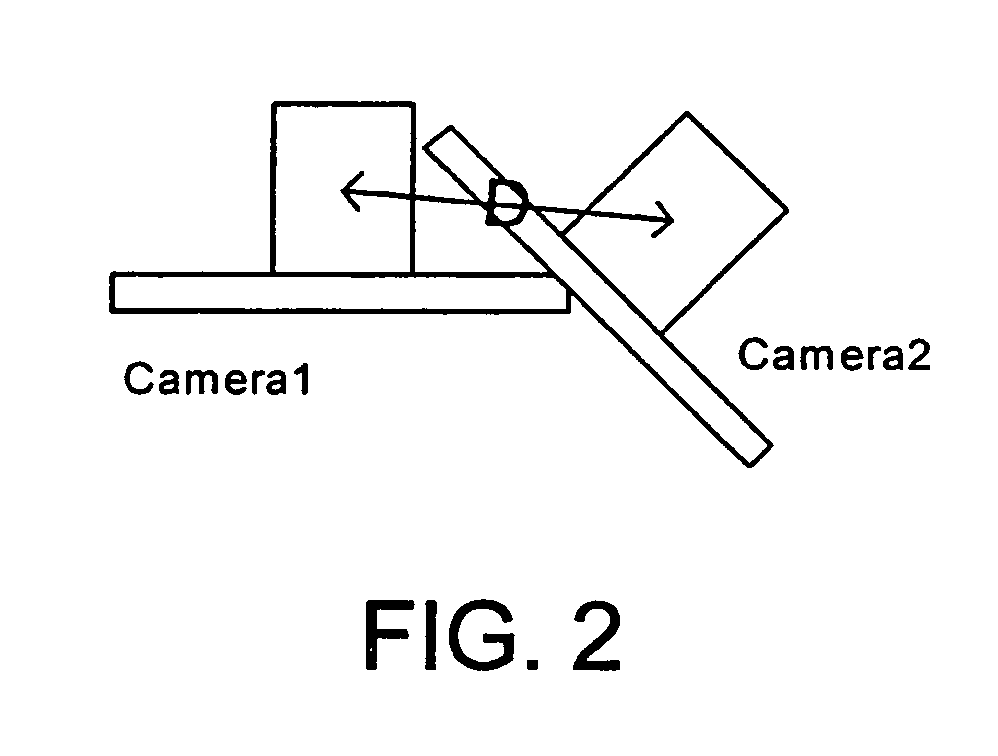
However, in some omni-directional camera configurations, D is much greater than zero, which results in motion parallax in the captured images.
Computing reliable object depth with stereo image pairs is a very difficult problem, and has not been solved generally (for arbitrary objects, texture, lighting, etc.).
The main problem with this method is that objects that are not near the calibration surface, and therefore not stitched correctly, are blended together to create a “ghost” image of the object.
If face detection information is available, then face regions are given an extra cost to prevent a path that divides a face between two cameras.

Method used


Image

  • System and method for camera calibration and images stitching
  • System and method for camera calibration and images stitching
  • System and method for camera calibration and images stitching

Examples


Embodiment Construction

[0033]In the following description of the preferred embodiments of the present invention, reference is made to the accompanying drawings which form a part hereof, and in which is shown by way of illustration specific embodiments in which the invention may be practiced. It is understood that other embodiments may be utilized and structural changes may be made without departing from the scope of the present invention.

1.0 Exemplary Operating Environment

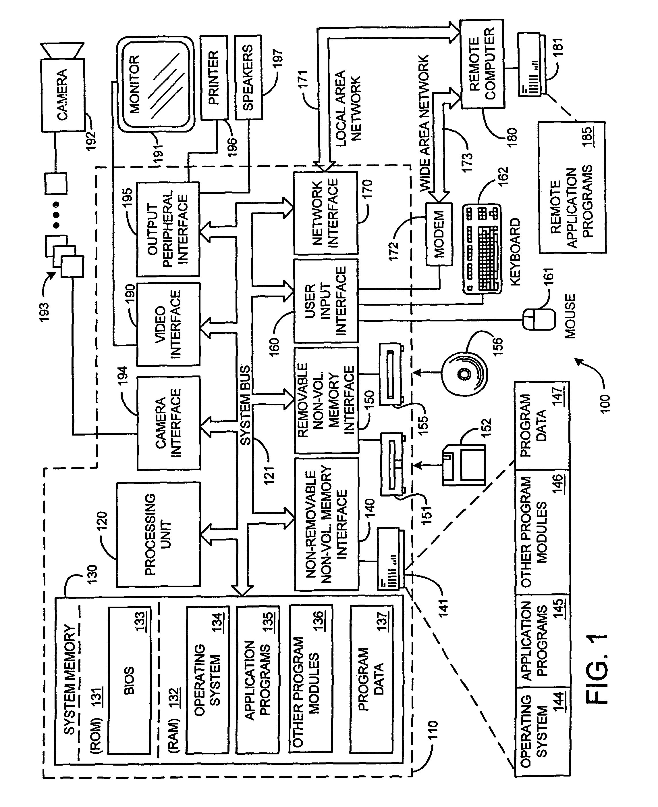
[0034]FIG. 1 illustrates an example of a suitable computing system environment 100 on which the invention may be implemented. The computing system environment 100 is only one example of a suitable computing environment and is not intended to suggest any limitation as to the scope of use or functionality of the invention. Neither should the computing environment 100 be interpreted as having any dependency or requirement relating to any one or combination of components illustrated in the exemplary operating environment 100.

[0035]The invent...


PUM


Abstract

A practical, real-time calibration of digital omnidirectional cameras in the areas of de-vignetting, brightness, contrast, and white balance control. Novel solutions for the color calibration of an omnidirectional camera rig, and an efficient method for devignetting images are presented. Additionally, a context-specific method of stitching images together into a panorama or a mosaic is provided.

Description

CROSS-REFERENCE TO RELATED APPLICATIONS[0001]This application is a continuation of Ser. No. 10 / 177,315 filed Jun. 21, 2002, now U.S. Pat. No. 7,259,784 entitled “A SYSTEM AND METHOD FOR CAMERA COLOR CALIBRATION AND IMAGE STITCHING”.BACKGROUND[0002]1. Technical Field[0003]This invention is directed toward a color calibration technique and a stitching technique for use with an omni-directional camera. More specifically, this invention is directed towards a system and method for improving the color uniformity of a composite image generated from a set of images depicting different but overlapping portions of the same scene. In addition, it includes a context-specific image stitching system and method that uses domain knowledge to improve the quality of image stitching.[0004]2. Background Art[0005]An image mosaic or panorama can be generated by aligning and “stitching” input images that are acquired from a single camera. To create an optimal panoramic stitched image, several types of col...

Claims


Application Information

Patent Timeline
Patent Type & Authority Patents(United States)
IPC IPC(8): H04N5/232G03B37/00G06T1/00G06T3/00G06T5/40G06T7/00H04N1/387H04N1/60H04N5/225H04N5/265H04N9/73H04N17/00
CPCG06T5/008G06T5/40G06T7/0024H04N17/002H04N1/3876H04N1/6027H04N5/23238H04N5/247G06T2200/32G06T2207/20221H04N9/73G06T2207/30201G06T7/30H04N23/698H04N23/90G06T5/94H04N23/88
Inventor CUTLER, ROSS
Owner MICROSOFT TECH LICENSING LLC
Learn More