
Battery cell protection and conditioning circuit and system

a battery cell and circuit technology, applied in the field of battery cell protection and conditioning circuit and system, can solve the problems of new safety, performance and efficiency, early termination of overall battery discharge operation, and far presented serious safety and cost drawbacks, and achieve the effects of optimizing the performance enhancing the safety of the battery pack, and reducing the cos

Active Publication Date: 2011-05-03
SENSATA TECHNOLOGIES INC
View PDF31 Cites 15 Cited by
  • Summary
  • Abstract
  • Description
  • Claims
  • Application Information

AI Technical Summary

Benefits of technology

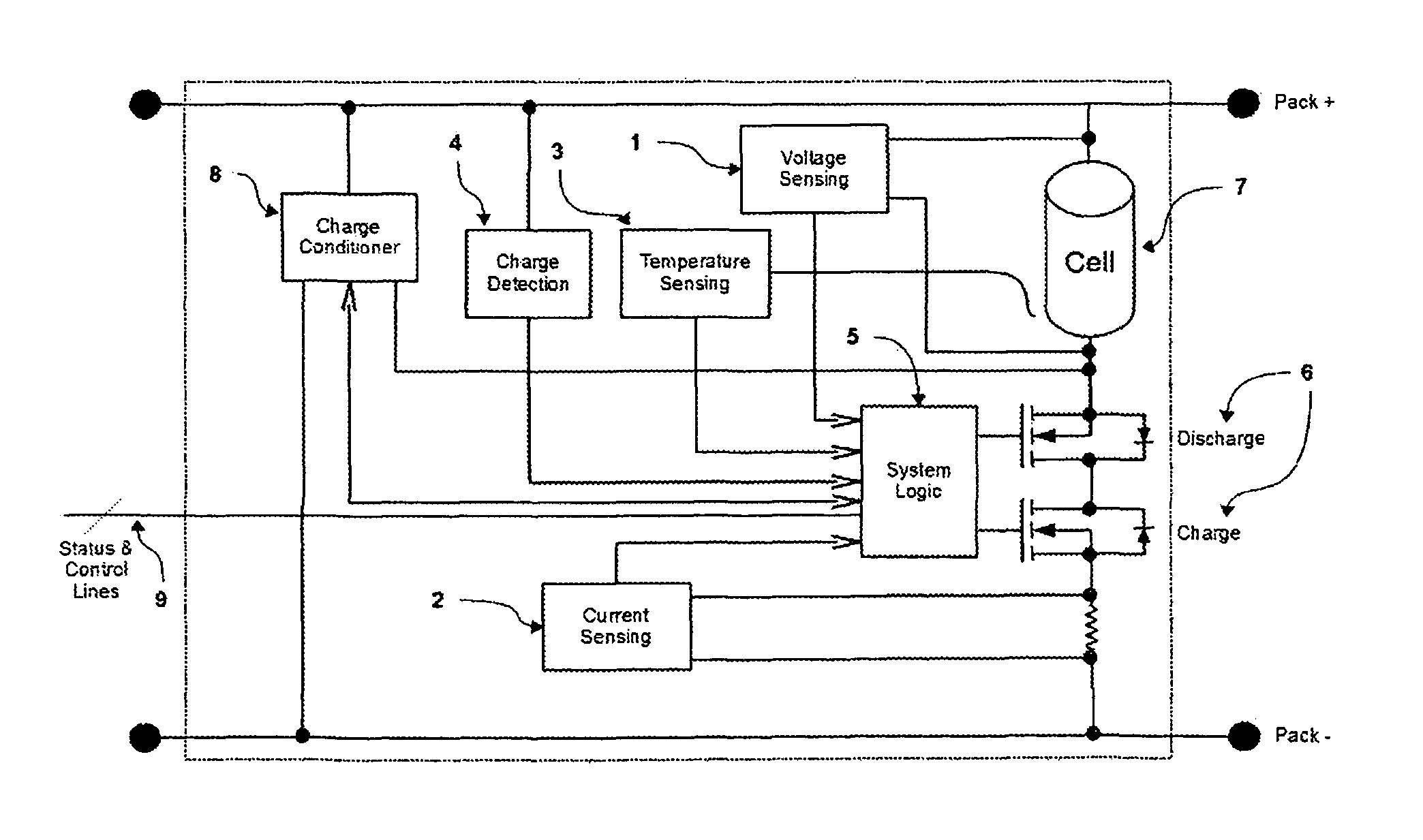
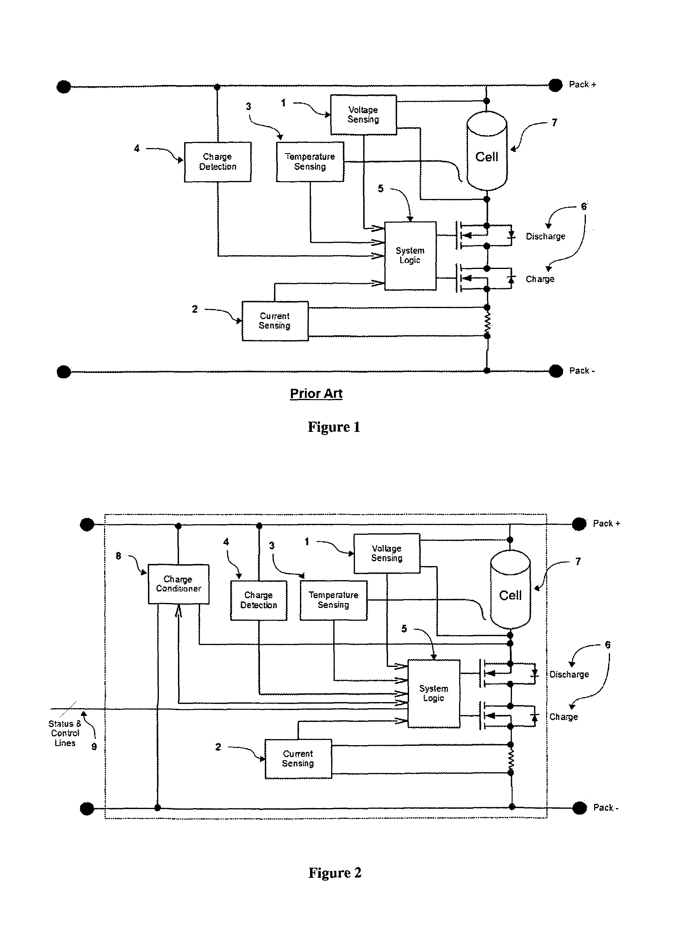
[0007]This proposed new type of protection and cell conditioning circuit partly uses the typically existing hardware present in traditional cell-protection circuits and that can achieve an optimum state of charge for the individual cell independently from the actions of the external battery charger. For minimum cost, the proposed circuit and system can solve the battery-cell-balancing problem, while optimizing the performance of the battery pack and while simultaneously enhancing the safety of the battery pack. Each individual cell within a battery pack has its own cell-protection circuitry, which is designed to autonomously control the final stage of the individual battery-cell charge. Multiple battery cells can be communicatively combined to form large batteries. Information from and commands to each of the individual battery cells can be relayed through a low-power serial bus in order to form “intelligent” and optimally managed battery systems.

Problems solved by technology

The combination of lithium-ion cells in order to create large-scale batteries gives rise to a new set of safety, performance, and efficiency problems.
One of the most significant problems relating to the performance and safety of the pack has to do with the fact that cells connected in series differ in capacity.
It is obvious that series-connected cells that do not start at the same state of charge will also discharge out of sync, resulting in a early termination of overall battery discharge operations when additional battery capacity should have been available.
This protection circuit is currently used as a stand-alone unit that act unsupervised in situations that threaten battery-pack safety.
However, the methods such as that described above to solve this problem have thus far presented serious safety and cost drawbacks.
Consequently, those proposed methods have failed to be adopted in the industry.

Method used


Image

  • Battery cell protection and conditioning circuit and system
  • Battery cell protection and conditioning circuit and system
  • Battery cell protection and conditioning circuit and system

Examples


first embodiment

[0012]Refer to FIG. 1, which illustrates the functional blocks of a traditional lithium-ion battery-protection circuit. The protection circuit typically includes a voltage sensor [1] that will detect an over-voltage condition during charging, or an under-voltage condition during discharging or when in storage. A current sensor [2] monitors current through the battery cell [7] in order to prevent discharge or charge currents from exceeding specific safety values. A temperature sensor [3] is used during charging to detect cell overheating. A charge-detection circuit [4] detects the presence of a charger in order to initiate and control the charging process. All of this information is collected and processed in the system-logic module, which controls a set of switches [6] that can turn open or close the charging or discharging current path. This protection circuit is currently used as a stand-alone unit that act unsupervised in situations that threaten battery-pack safety.

[0013]In mult...

second embodiment

ng and Conditioning Battery Cells

[0019]This embodiment encompasses a system for charging and conditioning the cells in a battery bank. The battery bank comprises a plurality of cells in connected in series, each of the plurality of cells defining a respective condition of charge. The system has an external constant-voltage / constant-current (CV / CC) battery charger. Each individual cell in the battery bank has a cell-protection circuit, with each of cell-protection circuits having a charge detector, a voltage sensor, a sensor for detecting charging current and discharging current, and switches for opening or closing the discharging or charging current path through the associated individual battery cell. Each cell-protection circuit further comprises a charge conditioner, with the charge conditioner being a constant-voltage-limited-current charger that is externally controlled and used when the associated battery cell reaches a predetermined state of charge from the external CV / CC batt...

third embodiment

ing and Conditioning Battery Cells

[0034]This embodiment encompasses a method for charging and conditioning the cells in a battery bank. The battery bank comprises a plurality of cells connected in series, each of the plurality of cells defining a respective condition of charge. The method comprises the step of providing a system having an external constant-voltage / constant-current (CV / CC) battery charger. Each individual cell within the battery bank has a cell-protection circuit, with each of the cell-protection circuits having a charge detector, a voltage sensor, a sensor for detecting charging current and discharging current, and switches for opening or closing the discharging or charging current path through said associated individual battery cell.

[0035]The method further comprises the step of providing in each cell-protection circuit a charge conditioner, with the charge conditioner being a constant-voltage-limited-current charger that is externally controlled and used when said...


PUM


Abstract

A type of protection and cell conditioning circuit is proposed that partly uses the typically existing hardware present in traditional cell-protection circuits and that can achieve an optimum state of charge for the individual cell independently from the actions of the external battery charger. For minimum cost, the proposed circuit and system can solve the battery-cell-balancing problem, while optimizing the performance of the battery pack and while simultaneously enhancing the safety of the battery pack. Multiple battery cells can be communicatively combined to form large batteries. Information from and commands to each of the individual battery cells can be relayed through a low-power serial bus in order to form “intelligent” and optimally managed battery systems.

Description

CROSS-REFERENCE TO RELATED APPLICATIONS[0001]This application claims the benefit of U.S. application No. 61 / 164,894, filed Mar. 30, 2009, which application is incorporated herein by reference for all purposes.BACKGROUND OF THE INVENTION[0002]The combination of lithium-ion cells in order to create large-scale batteries gives rise to a new set of safety, performance, and efficiency problems. One of the most significant problems relating to the performance and safety of the pack has to do with the fact that cells connected in series differ in capacity. Ideally, the cells should be in sync and charged optimally to their respective maximum capacity. One proposed solution to sync the cells and reach this optimized charge is described in PCT Publication No. WO / 2008 / 137764, “Fine-Controlled Battery-Charging System”, to Sendyne Corp. et al. In addition, during discharge, the series-connected cells should all discharge to their cutoff voltage at the same time. Using today's technology, cells ...

Claims


Application Information

Patent Timeline
Patent Type & Authority Patents(United States)
IPC IPC(8): H02J7/00H02J7/04
CPCH02J7/0031H02J7/0022H01M10/441H01M10/052H02J7/0029Y02E60/10H02J7/0014H02J7/00308H02J7/00309
Inventor MILIOS, IOANNIS
Owner SENSATA TECHNOLOGIES INC
Learn More