
Vehicle and control method of vehicle

a technology of vehicle and control method, which is applied in the direction of propulsion parts, propulsion using engine-driven generators, braking components, etc., can solve the problems that the booster cannot utilize the negative pressure at the stop of the internal combustion engine, and the driver may therefore feel uncomfortable, so as to reduce the negative pressure, accurately set the braking force demand, and effectively use the regenerative braking force

Inactive Publication Date: 2011-05-03
TOYOTA JIDOSHA KK
View PDF26 Cites 17 Cited by
  • Summary
  • Abstract
  • Description
  • Claims
  • Application Information

AI Technical Summary

Benefits of technology

[0006]In the vehicle of the invention and the control method of the vehicle, there is a need of preventing the driver from feeling uncomfortable at the time of a braking operation. In the vehicle of the invention and the control method of the vehicle, there is also a need of ensuring satisfaction of a braking force demand required by the driver.
[0009]When the sum of the regenerative braking force produced by the motor and the operational braking force based on the operational pressure is sufficient for a braking force demand required by the driver and set in response to the driver's braking operation, the vehicle of the invention controls the motor and the fluid pressure braking structure to satisfy the set braking force demand by a total of the regenerative braking force and the operational braking force. When the sum of the regenerative braking force produced by the motor and the operational braking force based on the operational pressure is insufficient for the braking force demand set in response to the driver's braking operation, on the other hand, the vehicle of the invention controls the motor and the fluid pressure braking structure to satisfy the set braking force demand by a total of the regenerative braking force, the operational braking force, and a braking force based on the increased pressure of the operation fluid. The operational pressure of the operation fluid is produced according to the driver's braking operation and the negative pressure produced by the internal combustion engine. In the event of no generation of the negative pressure at a stop of the internal combustion engine or in the event of a decrease in negative pressure by any reason, the generated operational pressure is insufficiently low under application of an equivalent level of the driver's braking operation in the state of decreased negative pressure to the level of the driver's braking operation in the state of non-decreased negative pressure. The insufficient negative pressure may lead to dissatisfaction of the braking force demand by the sum of the regenerative braking force produced by the motor and the operational braking force based on the operational pressure. In such cases, the braking force based on the increased pressure of the operation fluid is additionally used to satisfy the braking force demand. Even when the level of the driver's braking operation in the state of decreased negative pressure is equivalent to the level of the driver's braking operation in the state of non-decreased negative pressure, such braking control ensures satisfaction of the braking force demand required by the driver. The vehicle of the invention thus desirably ensures satisfaction of the braking force demand required by the driver, while effectively preventing the driver from feeling uncomfortable at the time of the driver's braking operation in the state of decreased negative pressure.
[0010]In one preferable embodiment of the vehicle of the invention, the vehicle further includes: an operational pressure detection unit that detects the operational pressure; a negative pressure measurement unit that measures the negative pressure produced by the internal combustion engine; and a regenerative braking force setting module that sets a regenerative braking force obtainable by regeneration of the motor in response to the driver's braking operation. In the vehicle, the braking force demand setting module sets the braking force demand based on the detected operational pressure and the measured negative pressure, and the braking control module controls the pressurization unit based on a result of subtraction of the set regenerative braking force and an operational braking force based on the detected operational pressure from the set braking force demand. The vehicle of this aspect ensures accurate setting of the braking force demand required by the driver even in the event of a variation in negative pressure produced by the internal combustion engine. The vehicle of this aspect also adequately regulates the pressurization unit of the fluid pressure braking structure to satisfy the set braking force demand.
[0011]In another preferable embodiment of the vehicle of the invention, the regenerative braking force setting module sets the regenerative braking force obtainable by regeneration of the motor in response to the driver's braking operation based on a rotation speed of the motor and a state of charge of the accumulator unit. The vehicle of this aspect ensures adequate setting of the regenerative braking force producible by regeneration of the motor in response to the driver's braking operation and effectively uses the regenerative braking force produced by the motor. The effective use of the regenerative braking force desirably saves the energy required for pressurization of the operation fluid by the pressurization unit. The regeneration of the motor may be restricted according to the state of charge of the accumulator unit. Even when the regenerative braking force produced by regeneration of the motor decreases according to the state of charge of the accumulator unit, the vehicle of this aspect utilizes the braking force based on the increased pressure of the operation fluid to satisfy the braking force demand required by the driver.
[0013]In still another preferable embodiment of the vehicle of the invention, the internal combustion engine is capable of outputting power to a first axle, and the motor is capable of inputting and outputting power from and to a second axle different from the first axle. The vehicle further includes: a connection disconnection structure that connects and disconnects an output shaft of the internal combustion engine to and from the first axle, and the connection disconnection structure disconnects the output shaft of the internal combustion engine from the first axle and an operation of the internal combustion engine is stopped when a predetermined condition is satisfied. The regenerative braking of the motor with the stopped operation of the internal combustion engine desirably enhances the energy efficiency of the vehicle. In the event of an insufficient level of the negative pressure at the stop of the internal combustion engine, the vehicle of this aspect ensures satisfaction of the braking force demand required by the driver even when the level of the driver's braking operation in the state of decreased negative pressure is equivalent to the level of the driver's braking operation in the state of non-decreased negative pressure. The vehicle of this aspect thus improves the operability and the safety in the braking state, while enhancing the energy efficiency.
[0015]According to the control method of the vehicle of the invention, the insufficient negative pressure may lead to dissatisfaction of the braking force demand by the sum of the regenerative braking force produced by the motor and the operational braking force based on the operational pressure. In such cases, the braking force based on the increased pressure of the operation fluid is additionally used to satisfy the braking force demand. Even when the level of the driver's braking operation in the state of decreased negative pressure is equivalent to the level of the driver's braking operation in the state of non-decreased negative pressure, such braking control ensures satisfaction of the braking force demand required by the driver. The control method of the vehicle of the invention thus desirably ensures satisfaction of the braking force demand required by the driver, while effectively preventing the driver from feeling uncomfortable at the time of the driver's braking operation in the state of decreased negative pressure.

Problems solved by technology

In the case of application of the prior art braking device equipped with the booster utilizing the negative pressure of the internal combustion engine to the hybrid vehicle, the booster can not utilize the negative pressure at the stop of the internal combustion engine.
The driver may thus feel uncomfortable at the time of the braking operation.

Method used


Image

  • Vehicle and control method of vehicle
  • Vehicle and control method of vehicle
  • Vehicle and control method of vehicle

Examples


Embodiment Construction

[0026]One mode of carrying out the invention is described below as a preferred embodiment.

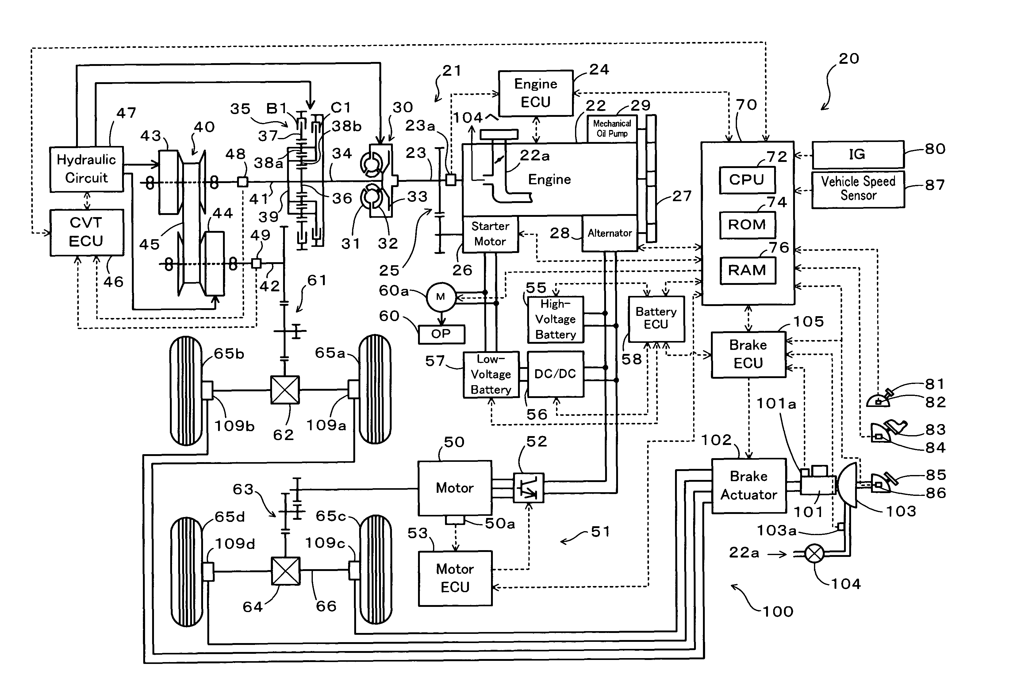
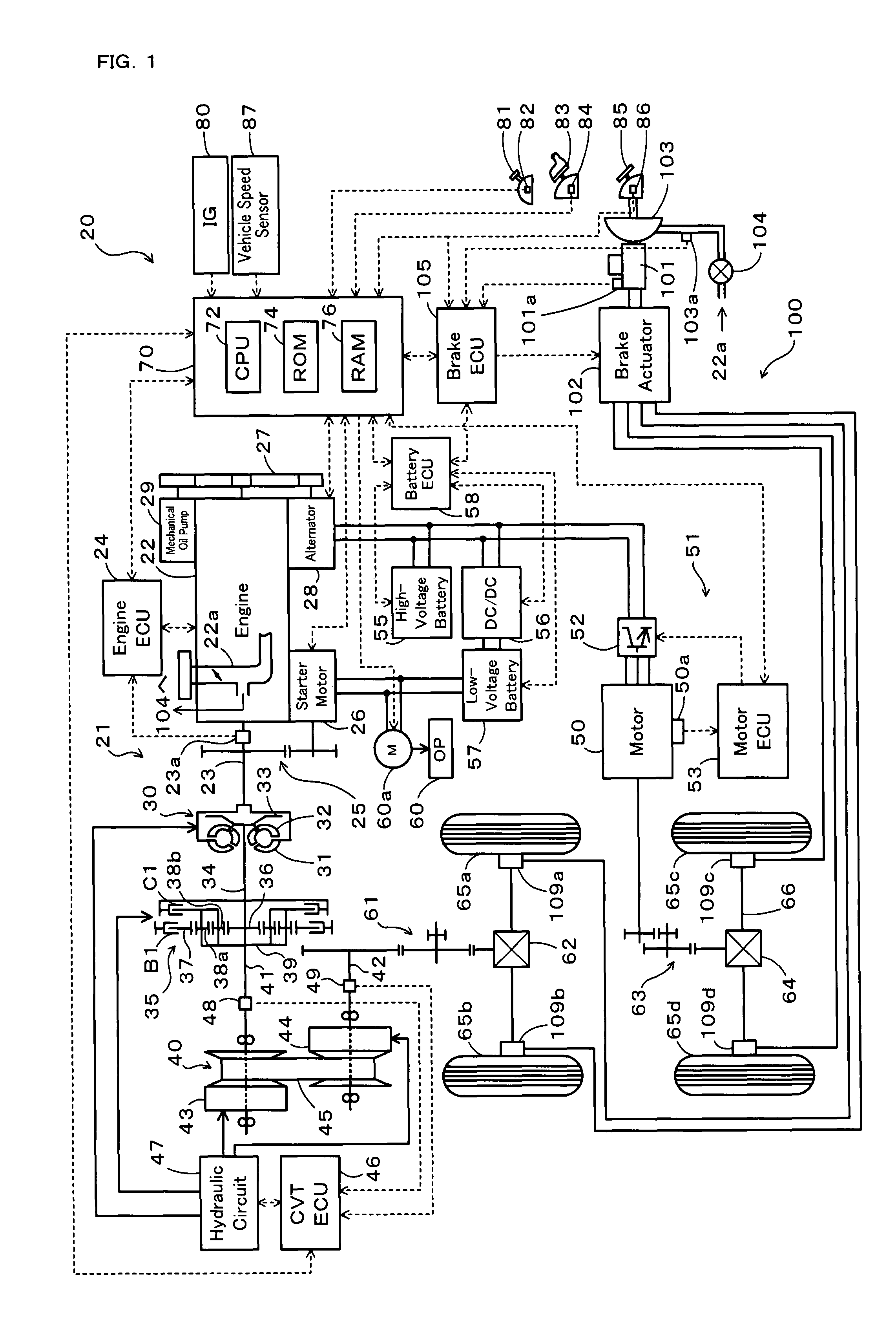
[0027]FIG. 1 schematically illustrates the configuration of a hybrid vehicle 20 of the invention. The hybrid vehicle 20 of the embodiment has a front wheel driving system 21 for transmission of output power of an engine 22 to front wheels 65a and 65b via a torque converter 30, a forward-backward drive switchover mechanism 35, a belt-driven continuously variable transmission (hereafter referred to as ‘CVT’) 40, a gear mechanism 61, and a differential gear 62, a rear wheel driving system 51 for transmission of output power of a motor 50 to rear wheels 65c and 65d via a gear mechanism 63, a differential gear 64, and a rear axle 66, an electronically controlled hydraulic braking system (hereafter referred to as ‘HBS’) 100 for application of braking force to the front wheels 65a and 65b and to the rear wheels 65c and 65d, and a hybrid electronic control unit (hereafter referred to as ‘hybrid ECU’) 7...


PUM


Abstract

In the hybrid vehicle of the invention, when the sum of a regenerative braking force BFr produced by a motor and an operational braking force BFpmc based on a master cylinder pressure Pmc is insufficient for a braking force demand BF* required by the driver in response to the driver's depression of a brake pedal, the motor and a brake actuator of an HBS are controlled to satisfy the braking force demand BF* by the total of the regenerative braking force BFr of the motor, the master cylinder pressure Pmc-based operational braking force BFpmc, and a compensated braking force BFpp based on a pressure increase by two pumps included in the brake actuator (steps S170 through S190).

Description

BACKGROUND OF THE INVENTION[0001]1. Field of the Invention[0002]The present invention relates to a vehicle and a control method of the vehicle. More specifically the invention pertains to a vehicle equipped with an internal combustion engine that outputs power and with a motor that is capable of outputting at least a regenerative braking force to an axle of the vehicle, as well as to a control method of such a vehicle.[0003]2. Description of the Related Art[0004]The known structure of a prior art braking device for the vehicle includes a booster that utilizes a negative pressure produced by an internal combustion engine to amplify the driver's pedal force of a brake pedal, a master cylinder that produces a fluid pressure according to the driver's pedal force amplified by the booster, an electric pump as a hydraulic pressure generation source, and wheel cylinders that use the master cylinder and the electric pump as the hydraulic pressure source to apply a braking force to correspond...

Claims


Application Information

Patent Timeline
Patent Type & Authority Patents(United States)
IPC IPC(8): B60T8/64B60T13/60B60K6/44B60K6/52B60K6/543B60L7/24B60L50/16B60T8/17B60W10/08B60W10/18B60W20/00
CPCB60K6/44B60K6/543B60T1/10B60T8/4872B60T13/586B60W10/08B60W10/184B60L1/003B60L7/26B60L11/123B60L11/14B60L11/1861B60L11/1868B60L15/2009B60K6/52Y02T10/642B60T2270/611B60W20/00B60W2540/12Y02T10/623Y02T10/6265B60L2210/10B60L2210/40B60L2240/12B60L2240/421B60L2240/423B60L2240/461B60L2240/545B60L2240/547B60L2240/549B60L2250/26B60L2260/28Y02T10/7077Y02T10/7044Y02T10/7005Y02T10/7241Y02T10/7066Y02T10/7275Y02T10/7216Y02T10/6217B60L50/61B60L50/16B60L58/12B60L58/20Y02T10/62Y02T10/64Y02T10/70Y02T10/72Y02T10/7072B60W10/26B60W20/13
Inventor KODAMA, SHINYASHIMADA, MICHIHITOMAKI, KAZUYA
Owner TOYOTA JIDOSHA KK
Learn More